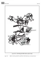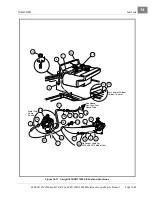
MC012C-BS00 UNITIZED TRANSAXLE WITH DIFFERENTIAL LOCK
Axle Shaft
2006-2010 Turf/Carryall 272/472 and XRT 1200/1200 SE Maintenance and Service Manual
Page 16-5
16
AXLE SHAFT, BEARING, AND OIL SEAL INSTALLATION
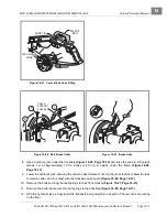
1. Replace the old oil seal with a new seal (89). Make sure the axle tube hub is free of debris.
2. Replace the old bearing with a new bearing (88). Slip the new bearing onto the machined journal, adja-
cent to the machined seal hub on the end of the axle
3. Clean the axle shaft and spline and carefully slide it through the axle seal, and advance until the splined
end meshes with the splined hub inside the gear box assembly, and the bearing slips into the axle tube
hub adjacent to the oil seal.
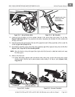
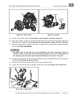
4. Use a 90° internal snap ring pliers and insert the internal retaining ring (87) into the groove in the axle
tube hub, adjacent to the outside surface of the bearing.
See following WARNING.
ý
WARNING
• Be sure retaining ring is properly seated in its groove. If ring is not properly installed, the axle
assembly will separate from the transaxle and damage the axle assembly and other
components. Loss of vehicle control could result in severe personal injury or death.
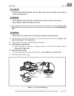
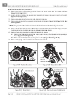
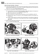
5. Install the wheel bolt flange (22) on the MC012C transaxle
.
See following
NOTE.
NOTE:
Clean splined components before axle installation. Use a small brush and carefully apply a light
coat of white lithium NLGI Number 2 grease (Dow Corning
®
BR2-Plus or equivalent) to splined
components before assembly.
5.1. Slide wheel bolt flange (22) onto splined end of the axle.
5.2. Slide the large flat washer (23) onto the end of the axle and up against the wheel bolt flange.
See
following NOTE.
NOTE:
It is recommended that a light film of white lithium NLGI Number 2 grease (Dow Corning BR2-Plus
or equivalent) be applied to both surfaces of the large washer (23) before the flanged nut (24) is
installed and tightened to specification.
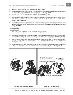
5.3. Attach the flanged nut (24) and tighten to 150 ft-lb (203 N·m).
5.4. Install the locking nut cap (27) onto the flanged nut (24) and position the locking nut cap (27) to pro-
vide clear passage for a new cotter pin (25).
5.5. Install a new cotter pin (25) through the locking nut cap and axle, bending the split ends of the pin
to secure the locking nut cap (27).
See following WARNING.
ý
WARNING
• Make sure to install and bend the cotter pin. Failure to bend the cotter pin could result in the
separation of the wheel bolt flange from the splined end of the axle. Loss of vehicle control
could result, causing severe personal injury.
5.6. Install the rubber boot (26) onto the large washer (23).
See following NOTE.
NOTE:
Push the rubber boot onto the washer so that the washer edge fits into the boot-lip groove.
5.7. Install the brake drum and wheel.
6. Repeat steps 2 through 5 for the remaining rear axle if necessary.
Summary of Contents for CARRYALL 272
Page 2: ......
Page 14: ......
Page 18: ...1...
Page 52: ...5...
Page 90: ...6...
Page 110: ...7...
Page 112: ...8...
Page 128: ...10...
Page 170: ...11...
Page 224: ...13...
Page 284: ...16...
Page 302: ...17...
Page 308: ......
Page 309: ...Club Car R NOTES...
Page 310: ...Club Car R NOTES...
Page 311: ......

