STEERING AND FRONT SUSPENSION
Rack and Pinion
Page 7-12
2006-2010 Turf/Carryall 272/472 and XRT 1200/1200 SE Maintenance and Service Manual
7
Rack and Pinion Assembly, Continued:
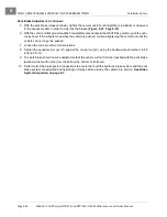
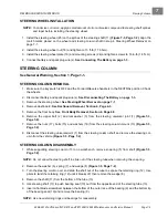
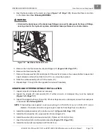
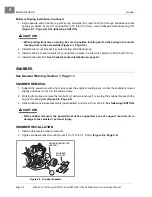
11. Insert a 3/8-inch, 1/4-drive, deep-well socket into the steering column end of the universal joint (2) and
tighten the bolts (1) to 15 ft-lb (20.3 N·m)
.
12. Use a torque wrench connected to the 3/8-inch deep-well socket to measure the resistance of the rack
and pinion. Rotational resistance should measure 7 to 15 in-lb (.8 to 1.7 N·m).
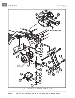
13. If measured resistance is not 7 to 15 in-lb (0.8 to 1.7 N·m), adjust the screw (7) until correct setting is
achieved. Tighten the nut (8) to 28 ft-lb (38 N·m)
.
NOTE:
When tightening the nut (8) make sure the screw (7) does not change adjustment
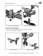
14. Install the two dust seal bellows (10).
15. Install new bellows clamps (wire ties) (11).
16. To minimize corrosion, apply a light coat of anti-seize lubricating compound to the ball joint threads.
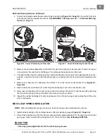
17. Loosely install the two nuts (12) and drag links (19). Advance drag links (19) and nuts (12) onto rack end
ball joints
. Nuts will be tightened during toe-in adjustment procedure.
18. Apply a light coat of anti-seize lubricating compound to the drag link threads.
19. Loosely install the two nuts (12) and ball joints (23). Advance ball joints (23) and nuts (12) into drag link
. Nuts will be tightened during toe-in adjustment procedure.
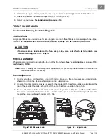
20. Apply a light coat of anti-seize lubrication to the universal joint and install it onto the pinion shaft and
tighten the bolt to 15 ft-lb (20 N·m).
RACK AND PINION INSTALLATION
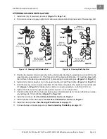
1. To minimize corrosion, apply a light coat of anti-seize and lubricating compound to the splined portion of
the steering column universal joint.
2. Align the flat portion of the shaft (1) spline with the bolt hole in the upper universal joint and then slide
the shaft into the universal joint. Install the bolt (27) and lockwasher (3) and tighten to 15 ft-lb (20.3 N·m)
3. Position the steering rack and pinion assembly on the vehicle frame, sliding the steering universal joint
up and through the hole in the mounting plate. Install the bolts (20), washers (21) and nuts (22). Using
a crisscross pattern, tighten the four nuts to 20 ft-lb (27.12 N·m)
Figure 7-22 Rack and Pinion Resistance
Figure 7-23 Install Ball Joint
2
3/8 INCH,
1/4 DRIVE,
DEEP WELL
SOCKET
1
Summary of Contents for CARRYALL 272
Page 2: ......
Page 14: ......
Page 18: ...1...
Page 52: ...5...
Page 90: ...6...
Page 110: ...7...
Page 112: ...8...
Page 128: ...10...
Page 170: ...11...
Page 224: ...13...
Page 284: ...16...
Page 302: ...17...
Page 308: ......
Page 309: ...Club Car R NOTES...
Page 310: ...Club Car R NOTES...
Page 311: ......

