ELECTRICAL COMPONENTS: FE400, KEY-START ENGINE
Starter/Generator (Model 114-01-4005)
Page 12-14
2006-2010 Turf/Carryall 272/472 and XRT 1200/1200 SE Maintenance and Service Manual
12
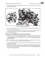
Disassembly of the Starter/Generator to Service the Armature/Commutator
1. Remove the commutator end cover to prevent damage to the brushes and armature.
of the Starter/Generator to Service the Brushes on page 12-11.
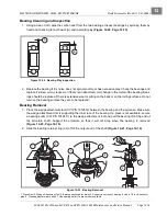
2. To separate armature and output end cover assembly from the field coil housing, first remove the two
securing bolts (43). Carefully remove armature and output end cover assembly from the field coil housing
so components are not damaged.
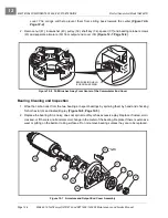
3. To separate armature (33) from output end cover (36), remove nut (41), lock washer (40), pulley (39). It
may be necessary to use the wedge attachment tool (CCI P/N 1012812) to remove the pulley from the
shaft.
4. Remove the internal retaining ring (32) to release the bearing (35) and armature (33) from the output end
.
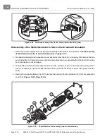
Figure 12-20 Pull Brushes Away from Center of the Commutator End Cover
Figure 12-21 Output End Cover Assembly, Armature and Housing
39
36
35
32
33
33
40
41
43
Summary of Contents for CARRYALL 272
Page 2: ......
Page 14: ......
Page 18: ...1...
Page 52: ...5...
Page 90: ...6...
Page 110: ...7...
Page 112: ...8...
Page 128: ...10...
Page 170: ...11...
Page 224: ...13...
Page 284: ...16...
Page 302: ...17...
Page 308: ......
Page 309: ...Club Car R NOTES...
Page 310: ...Club Car R NOTES...
Page 311: ......


