background image

MC012C-BS00 TRANSAXLE: HYDRAULIC AND PARK BRAKE SYSTEMS

Park Brake System

2006-2010 Turf/Carryall 272/472 and XRT 1200/1200 SE Maintenance and Service Manual

Page 6-33

6

PARK BRAKE SYSTEM

See General Warning, Section 1, Page 1-1.

PARK BRAKE CABLE REMOVAL
Equalizer Cable Removal

1. Chock the wheels and release the park brake.
2. Remove the two screws (3) that secure the park brake boot (2) to the seat support 

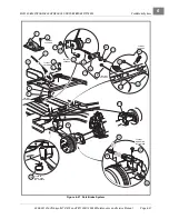
(Figure 6-27,

Page 6-37)

.

3. Slide the boot (2) off of the park brake handle (1).
4. Remove the boot shield (27) from the park brake handle.
5. Remove the equalizer spring (21) from the equalizer cable (9).
6. Remove the equalizer jam nut (11) and conical nut (23) from the cable end (9).
7. Remove the end of the park brake cable from handle (1) by pushing the equalizer cable in an upward

direction and pulling the cable end toward the passenger side of the vehicle.

8. Remove the equalizer cable from the vehicle.

Park Brake Pulley Removal

1. Remove the park brake equalizer cable. 

See Park Brake Cable Removal on page 6-33.

2. Remove the four #10-24 x 3/4-inch socket-head screws (14), locknuts (18) and washers (17) from frame

and remove the assembly 

(Figure 6-27, Page 6-37)

.

Wheel Brake Cable Removal

1. Loosen the equalizer jam nut (11) and the conical nut (23) to provide slack in the wheel brake cables

(Figure 6-27, Page 6-37)

.

2. Pull a wheel brake cable to the side and remove the cable end from the keyhole opening in the park brake

equalizer 

(Figure 6-25, Page 6-34 and Figure 6-26, Page 6-34)

.

3. Remove the cable clip (23) from a wheel brake cable (22) at the vehicle frame (25) 

(Figure 6-27,

Page 6-37)

.

4. Remove a park brake cable clip (12), hair spring cotter pin (20) and clevis pin (19).
5. Remove the cable from a cable support bracket (16 or 24).
6. Slide the cable through the frame hanger (15) and remove the cable from the vehicle.
7. Remove the remaining wheel brake cable in the same manner.

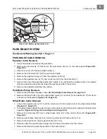
Figure 6-24   Master Cylinder Reservoir

WAR

NING

USE ONL

Y

DO

T 3 FLUID

FR

OM A

SEALED

CONT

AINER

MAX

MIN

USE

 O

N

L

Y


D

.  

O

.  

T

.  3

 F

LU

ID

 F

RO

M

 A

 S

E

A

L

E

D


CLEAN 

 F

IL

L

E

R

 C

A

PS

 B

EF

OR

E


MIN

MAX

Full

Level

Low

Level

Safe Level

Summary of Contents for CARRYALL 272

Page 1: ...Manual Number 102907711 Edition Code 1007B0810A Turf 272 Carryall 272 Carryall 472 XRT 1200 and XRT1200 SE Gasoline Vehicles 2006 2010 Turf Carryall 272 472 XRT1200 SE Maintenance and Service Manual...

Page 2: ......

Page 3: ...lub Car distributor dealer representative or by a Club Car factory trained technician It is the policy of Club Car LLC to assist its distributors and dealers in continually updating their service know...

Page 4: ...appear in future editions of this manual Damage to a vehicle or component thereof not resulting from a defect or that occurs due to unrea sonable or unintended use overloading abuse or neglect includi...

Page 5: ...Identification 3 1 Storage 3 2 Preparing The Vehicle For Extended Storage 3 2 To Return Vehicle To Service 3 3 SECTION 4 BODY AND TRIM Cleaning the Vehicle 4 1 Front Body Repair 4 2 Abrasions and Haze...

Page 6: ...14 Tailskirt 4 14 Tailskirt Removal 4 14 Tailskirt Installation 4 14 Trailer Hitch 4 15 Trailer Hitch Removal 4 15 Trailer Hitch Installation 4 15 Receiver Hitch 4 15 Receiver Hitch Removal 4 15 Recei...

Page 7: ...ster Assembly Installation 6 17 Rear Brake Cluster Assembly Removal 6 18 Rear Brake Cluster Assembly Installation 6 19 Wheel Cylinder Replacement 6 19 Front Wheel Cylinder Removal 6 19 Front Wheel Cyl...

Page 8: ...ustment 6 35 SECTION 7 STEERING AND FRONT SUSPENSION Steering Wheel 7 1 Steering Wheel Removal 7 1 Steering Wheel Installation 7 3 Steering Column 7 3 Steering Column Removal 7 3 Steering Column Disas...

Page 9: ...tallation 9 1 Multi Leaf Springs 9 1 Multi Leaf Spring Removal 9 1 Multi Leaf Spring Installation 9 3 Snubber 9 4 Snubber Removal 9 4 Snubber Installation 9 4 SECTION 10 PERIODIC MAINTENANCE Periodic...

Page 10: ...out Cam 12 28 Reverse Warning Buzzer 12 29 Reverse Buzzer Limit Switch 12 30 Oil Warning Light 12 30 Fuel Gauge Hour Meter 12 31 Fuel Level Sending Unit 12 32 RPM Limiter 12 33 Ignition Coil 12 34 Oil...

Page 11: ...6 Governor Cable 14 7 Accelerator Cable 14 8 Closed Throttle or Idle Adjustment 14 9 Engine RPM Adjustment 14 10 Choke and Air Intake System 14 12 Choke Cable Removal 14 12 Choke Cable Installation 14...

Page 12: ...eral Information 16 1 Lubrication 16 2 Axle Shaft 16 3 Axle Shaft Bearing and Oil Seal Removal 16 3 Axle Shaft Bearing and Oil Seal Installation 16 5 Unitized Transaxle Removal 16 6 Unitized Transaxle...

Page 13: ...h Cleaning and Inspection 17 5 Drive Clutch Disassembly 17 6 Inspection of Drive Clutch Parts 17 7 Drive Clutch Assembly 17 10 Drive Clutch Installation 17 11 Driven Clutch 17 12 Driven Clutch Removal...

Page 14: ......

Page 15: ...mage GENERAL WARNING The following safety procedures must be followed whenever the vehicle is being operated repaired or ser viced Service technicians should become familiar with these general stateme...

Page 16: ...ult in severe burns Use insulated tools when working near batteries or electrical connections Use extreme caution to avoid shorting of components or wiring Check the vehicle owner s manual for proper...

Page 17: ...le on page 1 3 2 Disconnect the battery cables negative cable first as shown Figure 1 1 Page 1 3 3 Disconnect the spark plug wire s from the spark plug s CONNECTING THE BATTERY 1 Connect the battery c...

Page 18: ...1...

Page 19: ...ferential lock feature Electrical system 12 volt 500 cca at 0 F 17 8 C 650 at 32 F 0 C 105 minute reserve capacity and 35 amp charging capacity Torque converter Automatic vari able speed dry type STEE...

Page 20: ...t 31 1 in 79 cm Load bed size box bed inside dimensions 48 0 x 49 8 x 9 3 in 121 9 x 126 4 x 24 cm 13 0 cubic feet 48 0 x 49 8 x 10 9 in 121 9 x 126 4 x 27 6 cm 13 0 cubic feet 37 6 x 45 1 x 9 3 in 96...

Page 21: ...ngine and key start with neutral rev See fol lowing NOTE NOTE 272 vehicles can be found custom ordered equipped with the non standard FE350 engine with pedal start SERIAL NUMBER IDENTIFICATION The ser...

Page 22: ...he Forward Reverse handle is in the NEUTRAL position Chock the wheels 5 Drain carburetor and seal the fuel tank 6 Turn the fuel shut off valve to the closed OFF position Figure 3 4 Page 3 4 and Figure...

Page 23: ...ERVICE 1 Make sure the key switch is OFF and the Forward Reverse handle is in the NEUTRAL position Remove the key Chock the wheels 2 Remove plug from vent tube and connect to tank vent Figure 3 2 Page...

Page 24: ...ff Valve 49 State Fuel Tank Figure 3 5 Fuel Shut off Valve California Fuel Tank 1 Fuel Shut off Valve 2 Closed OFF 3 Open ON NOTE When selecting valve position ensure that it is fully opened or fully...

Page 25: ...e grade No 00 steel wool Club Car does not recommend any type of pressure washing or steam cleaning Such a process will expose electrical components to moisture Moisture entering electrical components...

Page 26: ...carbide abrasive paper 320 grit or finer Use progressively finer grits i e 400 600 800 to reduce sanding marks Use Ajax cleanser or equivalent for final smoothing A Micro Mesh acrylic polishing kit wi...

Page 27: ...panel to access back of panel 4 Disconnect the wiring from components mounted in the dash panel 5 Remove five caps 1 from top of dashboard 2 Figure 4 2 Page 4 6 6 Remove screws 3 and special plastic w...

Page 28: ...BODY AND TRIM Front Body Components Page 4 4 2006 2010 Turf Carryall 272 472 and XRT 1200 1200 SE Maintenance and Service Manual 4 Figure 4 1 Dash Panel Removal A B...

Page 29: ...ets securing front fender 9 to frame Drill out two 3 16 x 5 8 pop rivets 10 and remove two washers 11 3 Use a 3 8 hex head socket to remove two screws 12 from fender frame support and remove fender FR...

Page 30: ...vice Manual 4 Figure 4 2 Front Body Assembly 10 11 TYPICAL 4 PLACES 5 TYPICAL 5 PLACES 7 TYPICAL 2 PLACES 6 2 12 9 9 15 14 FENDER SUPPORT 1 3 4 7 TYPICAL 6 PLACES TYPICAL 5 PLACES 11 TYPICAL 4 PLACES...

Page 31: ...ge 4 8 3 Adjust seat to preferred position Align holes in seat panel 3 with holes in seat 2 and secure with four bolts 4 and lockwashers 5 Tighten bolts to 96 in lb 10 8 N m See following WARNING WARN...

Page 32: ...le unless the vehicle is fitted with a structural cab 3 Connect differential lock cable to differential lock handle See step 33 of Unitized Transaxle Installa tion Section 16 Page 16 21 4 Install park...

Page 33: ...lifting the lower inside flange slightly across the entire seat area Push the trim toward the rear of the vehicle allowing the top flange to slide away from the seat frame toward the rear of the vehic...

Page 34: ...06 2010 Turf Carryall 272 472 and XRT 1200 1200 SE Maintenance and Service Manual 4 Figure 4 4 Carryall 472 XRT 1200 SE Rear Seat Support 14 12 13 17 10 16 TYPICAL 4 PLACES 18 19 11 22 TYPICAL 10 PLAC...

Page 35: ...3 8 inch hinge bolts 9 from the hinge assemblies 1 4 Raise rear edge of bed approximately 6 inches 15 2 cm and pull bed assembly toward rear of vehicle approximately 3 inches 7 6 cm to release bed lat...

Page 36: ...age 4 12 2006 2010 Turf Carryall 272 472 and XRT 1200 1200 SE Maintenance and Service Manual 4 Figure 4 5 Turf CA 272 XRT 1200 Cargo Bed 4 3 25 11 2 17 TYPICAL 4 PLACES 16 19 TYPICAL 2 PLACES 18 10 TY...

Page 37: ...d onto vehicle and align frame hinge brackets 3 with bed hinge brackets 4 2 3 Start the bolts 1 into left and right hinge assemblies Use an alignment tool if necessary 2 4 Use a small hammer to lightl...

Page 38: ...ender washers 4 and 1 4 20 x 1 inch hex head bolts 3 attaching the fender wall 1 to the vehicle frame 4 Remove fender 1 from the vehicle 5 Repeat steps 1 through 4 for removal of the opposite fender i...

Page 39: ...all 272 XRT 1200 1 1 Reverse the trailer hitch removal process and tighten bolts to 15 ft lb 20 3 N m Figure 4 7 Page 4 16 1 2 Install the tailskirt See Tailskirt Installation on page 4 14 RECEIVER HI...

Page 40: ...aintenance and Service Manual 4 Figure 4 7 Turf 272 Carryall 272 XRT 1200 Rear Fender Tailskirt and Trailer Hitch 7 19 TYPICAL 2 PLACES 1 2 5 4 4 3 6 TYPICAL 2 PLACES 10 5 4 3 TYPICAL 4 PLACES 8 9 3 5...

Page 41: ...1200 SE Maintenance and Service Manual Page 4 17 4 Figure 4 8 Carryall 472 XRT 1200 SE Rear Fender Tailskirt and Receiver Hitch 7 8 TYPICAL 2 PLACES 2 5 4 4 3 6 TYPICAL 2 PLACES 10 9 11 1 5 4 3 TYPICA...

Page 42: ...he corner where the rear seat frame meets the floorboard and roll the mat corner toward the center of the vehicle from under the side support angle pulling it diagonally from the vehicle FLOOR MAT INS...

Page 43: ...Use approved jack stands of proper weight capacity to support the vehicle and chock the wheels that remain on the floor When not performing a test or service procedure that requires movement of the w...

Page 44: ...arryall 272 472 and XRT 1200 1200 SE Maintenance and Service Manual 5 Figure 5 1 Brake Pedal Assembly UND ER 16 STOP TYPICAL 4 PLACES TYPICAL 2 PLACES TYPICAL 4 PLACES FLOORBOARD REMOVED FOR CLARITY 1...

Page 45: ...top jam nut 31 Figure 5 4 Page 5 3 4 Pull the brake pedal toward the rear of the vehicle until the brake stop bumper will not allow the pedal to travel any further Figure 5 5 Page 5 3 5 Holding the br...

Page 46: ...crank assembly 11 Figure 5 1 Page 5 2 See following NOTE NOTE The spring 17 should not be under tension while the brake pedal is at rest 9 Install the bow tie locking pin 21 10 There should be at lea...

Page 47: ...11 assem bly 7 Slide the spring retainer 11 off of the accelerator pivot rod 8 Inspect the pivot support bearing 9 inside the spring retainer for wear and replace if necessary 9 Remove locknut 26 from...

Page 48: ...page 1 3 ACCELERATOR PEDAL ADJUSTMENT See General Warning Section 1 Page 1 1 1 Measure the distance from the top of the accelerator pedal to the floorboard If it is within the range of 5 3 4 inches 1...

Page 49: ...r than 16 years old Do not leave childern unatten ded on vehicle UND ER 16 WAR NING WAR NING ROLLO VER OR FALLIN G OFF MAY CAUSE DEATH Read operato rs manual and operatin g instruct ions Remain seated...

Page 50: ...10 Page 5 8 See following NOTE NOTE After the accelerator pedal and rod are adjusted the final governed engine RPM should be set to FE400 Engine 3850 30 RPM See Engine RPM Adjustment Section 14 Page 1...

Page 51: ...2010 Turf Carryall 272 472 and XRT 1200 1200 SE Maintenance and Service Manual Page 5 9 5 Figure 5 11 Accelerator Pedal Assembly FLOORBOARD REMOVED FOR CLARITY TYPICAL 4 PLACES 26 22 21 24 TYPICAL 4 P...

Page 52: ...5...

Page 53: ...heavy pressure to the pedal and check for sponginess and excessive pedal travel The pedal should be firm and the back of the brake pedal should be a minimum of 2 inches from the floor If the brake pe...

Page 54: ...r backing plate for signs of brake fluid leakage If so deter mine the cause of the leak and replace the brake hose or wheel cylinder See Wheel Cylinder Replacement on page 6 19 Also See Hydraulic Line...

Page 55: ...prings Replace damaged items If the brake adjusters 3 are frozen requiring more than 65 in lb 7 4 N m to turn freely worn or loose replace the adjuster assemblies in pairs Figure 6 1 Page 6 2 See Brak...

Page 56: ...b or axle seal and replace the brake shoes See Brake Shoe Removal on page 6 8 Glazed brake shoe linings Replace the brake shoes See Brake Shoe Removal on page 6 8 Damaged or distorted brake shoes Repl...

Page 57: ...ings Sticking wheel cylinder piston Replace the wheel cylinder See Wheel Cylinder Replacement on page 6 19 Overly adjusted brake adjusters Adjust brake adjusters See Brake Shoe Adjuster Replacement on...

Page 58: ...ge 6 7 4 2 Remove the castle nut 3 large flat washer 4 wheel bearing 5 and drum 8 If the brake drum was easily removed proceed to step 6 Rear brakes drag Binding park brake cables Adjust or replace ca...

Page 59: ...adjuster bolts to increase the clearance between the brake shoe lining and the brake drum Figure 6 3 Page 6 7 See following NOTE NOTE If the adjusters require more than 65 in lb 7 3 N m of force to ro...

Page 60: ...uire more than 65 in lb 7 3 N m of force to rotate they must be replaced See Brake Shoe Adjuster Replacement on page 6 21 5 3 Rotate the brake drum slightly to remove it from the brake shoe cluster as...

Page 61: ...de the wheel bolt flange 22 off of the splined axle end 5 Use pliers or a brake tool to rotate the cup washer and compression spring assembly 90 and remove the cup and spring from each brake shoe Figu...

Page 62: ...ake cluster assembly for proper operation 4 1 Locate the bolt heads of the two brake shoe adjusters on the back of each brake cluster assembly 4 2 Use a torque wrench and a Torx T 27 driver or hydraul...

Page 63: ...equivalent on each of the six raised bosses on the back plate Figure 6 9 Page 6 11 See preceding WARNING 11 Brush a light coat of white lithium NLGI Number 2 grease Dow Corning BR2 Plus or equivalent...

Page 64: ...to secure the brake shoe Figure 6 4 Page 6 9 6 After the shoes are installed move them together up and down approximately 1 4 to 3 8 inch 6 3 to 9 5 mm to make sure that they will slide easily withou...

Page 65: ...g BR2 Plus or equivalent to both prior to assembly 8 1 Slide wheel bolt flange 22 onto splined axle Figure 6 5 Page 6 9 8 2 Slide the large flat washer 23 onto the end of the axle and up against the w...

Page 66: ...NOTE Prior to installing the brake drum inspect the brake lines hoses drums and brake cluster assem blies See Brake System Inspection on page 6 1 Clean any residual grease from the friction area of th...

Page 67: ...TION and NOTE WARNING Make sure to install and bend the cotter pin Failure to bend the cotter pin could result in the separation of the wheel from the spindle Loss of vehicle control could result caus...

Page 68: ...and gen tly rotate the adjuster bolts to increase the clearance between the brake shoe lining and the brake drum Figure 6 14 Page 6 16 See following NOTE NOTE If the adjusters require more than 65 in...

Page 69: ...DOT 5 brake fluid See Bleeding the Hydraulic Brake System on page 6 31 Worn or damaged brake drums must not be machined Replace as necessary Use only approved replacement brake drums designed for you...

Page 70: ...REMOVAL 1 Remove rear brake drum See Rear Wheel Brake Drum Removal on page 6 8 2 Remove rear brake shoes See Rear Brake Shoe Removal on page 6 8 3 Remove park brake cable clip 1 hair spring cotter pi...

Page 71: ...pin 3 and hair spring cotter pin 2 5 Install rear brake shoes See Rear Brake Shoe Installation on page 6 12 6 Install rear wheel brake drum See Rear Wheel Brake Drum Installation on page 6 16 7 Repea...

Page 72: ...Hydraulic Brake System on page 6 31 7 Perform all of the brake system inspections See Brake System Inspection on page 6 1 REAR WHEEL CYLINDER REMOVAL 1 Remove rear wheel brake drum See Rear Wheel Brak...

Page 73: ...kes must be bled after the correct installation of the brake components Failure to bleed the brakes could result in decreased braking performance due to air being trapped in the hydraulic system Use o...

Page 74: ...nting post is to the top of the back plate 4 Grip adjuster arm 3 with a pair of locking pliers and tighten the bolt 4 to 115 in lb 13 N m 5 Repeat steps 1 through 4 for the remaining adjuster 6 Instal...

Page 75: ...ystem must be opened As a result the brakes must be bled after the correct installation of the brake components Failure to bleed the brakes could result in decreased braking performance due to air bei...

Page 76: ...t wrench to remove the brake line 4 from the T manifold block 1 Figure 6 20 Page 6 26 7 Remove the bolt 2 washer 13 and locknut 3 that secure the T manifold block 1 to the shock tower FRONT BRAKE HOSE...

Page 77: ...6 1 2 Install the opposite end of the brake line to the master cylinder and tighten the flare nut fitting to 11 ft lb 14 9 N m Figure 6 20 Page 6 26 1 3 Repeat steps 1 1 through 1 2 for the opposite r...

Page 78: ...from the rear brake hose at the I beam of the vehicle frame Figure 6 20 Page 6 26 or Figure 6 21 Page 6 27 6 Remove the horseshoe clip 12 that secures the rear brake hose 9 to the I beam frame and re...

Page 79: ...200 SE Maintenance and Service Manual Page 6 27 6 Figure 6 21 Carryall 472 XRT 1200 SE Four Wheel Hydraulic Brake System TYPICAL 2 PLACES TYPICAL BOTH SIDES TYPICAL BOTH SIDES 5 7 8 14 14 9 2 18 17 10...

Page 80: ...ll crank 2 Remove brake rod clevis pin 6 bow tie locking pin 8 and clevis 16 from the bell crank 13 Figure 6 22 Page 6 30 3 Remove the spring 18 from the bell crank 13 and master cylinder mounting bra...

Page 81: ...master cylinder 1 Figure 6 22 Page 6 30 9 Remove master cylinder 1 from mounting bracket 19 push rod 3 and rubber boot 2 MASTER CYLINDER INSTALLATION 1 Install master cylinder 1 into mounting bracket...

Page 82: ...ement Page 6 30 2006 2010 Turf Carryall 272 472 and XRT 1200 1200 SE Maintenance and Service Manual 6 Figure 6 22 Master Cylinder 1 5 4 7 TYPICAL 2 PLACES 18 19 20 11 8 TYPICAL 2 PLACES 3 6 13 2 8 12...

Page 83: ...y of the adjuster bolts Over tightening the adjuster bolts could result in damage to the brake cluster components or the separation of the bolt 4 from the adjuster 3 Figure 6 1 Page 6 2 or Figure 6 19...

Page 84: ...Brake System on page 6 31 2 Allow 1quart 0 9464 l of the brake fluid to be pulled into the vacuum type brake bleeder tool 3 With the vacuum still running tighten the two brake bleeder valves 4 Allow...

Page 85: ...able See Park Brake Cable Removal on page 6 33 2 Remove the four 10 24 x 3 4 inch socket head screws 14 locknuts 18 and washers 17 from frame and remove the assembly Figure 6 27 Page 6 37 Wheel Brake...

Page 86: ...6 27 Page 6 37 2 Assemble the equalizer bracket 10 onto the threaded end of the equalizer cable 9 3 Attach the conical nut 23 and equalizer jam nut 11 to the threaded end of the equalizer cable 4 Att...

Page 87: ...on page 6 34 3 Adjust the park brake See Park Brake Adjustment on page 6 35 4 Perform all of the brake system inspections See Brake System Inspection on page 6 1 PARK BRAKE ADJUSTMENT CAUTION Perform...

Page 88: ...d If the wheels move when the vehicle is pushed continue tightening the conical nut until the vehicle can no longer be pushed 7 Loosen the conical nut two full revolutions 8 Tighten the equalizer jam...

Page 89: ...SE Maintenance and Service Manual Page 6 37 6 Figure 6 27 Park Brake System ClubCar 23 11 4 5 TYPICAL 2 PLACES 1 27 5 6 TYPICAL 2 PLACES TYPICAL EACH SIDE OF VEHICLE 15 20 TYPICAL EACH SIDE OF VEHICL...

Page 90: ...6...

Page 91: ...ositioning 5 Loosen the steering wheel nut 18 and back it off approximately 1 4 inch 6 mm Do not remove the nut 6 Use the steering wheel puller CC P N 102061201 to remove steering wheel 6 1 Place the...

Page 92: ...ge 7 2 2006 2010 Turf Carryall 272 472 and XRT 1200 1200 SE Maintenance and Service Manual 7 Figure 7 3 Steering Column 17 16 TYPICAL 4 PLACES 15 TYPICAL 4 PLACES 13 14 19 18 24 11 10 10 9 8 7 6 5 1 3...

Page 93: ...1 4 Remove dashboard See Dashboard Removal Section 4 Page 4 3 5 Remove the front body See Front Body Removal Section 4 Page 4 5 6 Remove the upper bolt 2 and lockwasher 3 from the steering universal j...

Page 94: ...wedge 8 will ride against the inner race of the bearing 3 Install the wedge 8 spring 7 washer 6 and snap ring 5 onto the bottom end of the steering shaft 11 Figure 7 5 Page 7 5 4 Insert the shaft 11 f...

Page 95: ...washers 16 and locknuts 17 Figure 7 3 Page 7 2 Tighten the four bolts in a crisscross pattern to 23 ft lb 31 2 N m 6 Tighten the bolt 2 on the upper steering universal joint 1 to 15 ft lb 20 N m 7 Che...

Page 96: ...Replace the rack and pinion as an assembly if any is found In the event of an known impact and obvious visible damage is not found in the method described above dis connect the tie rods and or drag li...

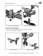
Page 97: ...tenance and Service Manual Page 7 7 7 RACK AND PINION DISASSEMBLY 1 Remove the two ball joints and inspect for excessive wear Figure 7 9 Page 7 7 2 Remove both drag links Figure 7 10 Page 7 7 Figure 7...

Page 98: ...the bolt and then sliding off the uni versal joint Figure 7 12 Page 7 8 7 Remove the dust seal Figure 7 13 Page 7 8 8 Remove the snap ring Figure 7 14 Page 7 9 9 Install the universal joint back onto...

Page 99: ...3 Remove the ball joint 9 from the rack 2 Figure 7 19 Page 7 10 12 Remove the rack 2 from housing 1 13 Inspect the bushing 17 and needle bearing 14 for excessive wear If wear is excessive replace the...

Page 100: ...6 2010 Turf Carryall 272 472 and XRT 1200 1200 SE Maintenance and Service Manual 7 Figure 7 19 Steering Gear 13 4 15 17 22 3 16 2 23 12 19 12 11 10 24 9 18 TYPICAL 4 PLACES TYPICAL 2 PLACES 20 21 5 6...

Page 101: ...bber mallet See following CAUTION CAUTION Do not force the pinion bearing assembly into the housing The gear teeth or the small bearing could be damaged 4 Install the snap ring 4 5 Use a socket to app...

Page 102: ...re 7 19 Page 7 10 Nuts will be tightened during toe in adjustment procedure 18 Apply a light coat of anti seize lubricating compound to the drag link threads 19 Loosely install the two nuts 12 and bal...

Page 103: ...e 1 1 WHEEL ALIGNMENT Wheel alignment is limited to adjusting the toe in of the front wheels See Toe in Adjustment on page 7 13 See following NOTE NOTE Prior to making any front suspension adjustments...

Page 104: ...ball joint to the end of the threads on each drag link Figure 7 26 Page 7 14 6 4 Tighten the locknuts 24 to 40 ft lb 54 N m Figure 7 19 Page 7 10 7 Check the toe in If toe in is not adjusted properly...

Page 105: ...0 off of the A arm 13 9 Repeat steps 1 through 8 for the opposite front wheel if necessary KINGPIN AND STEERING SPINDLE INSTALLATION 1 Inspect all parts and replace them as necessary 2 Inspect the kin...

Page 106: ...e lower shock absorber mounting bolt 2 nut 3 and steering stop bracket 34 8 Remove the two bolts 10 two nuts 11 and the A arm 13 from the suspension mounting plate 9 Repeat steps 1 through 8 for the o...

Page 107: ...Suspension 15 TYPICAL 2 PLACES 14 TYPICAL 4 PLACES 16 32 33 2 34 22 1 35 2 TYPICAL 2 PLACES 4 TYPICAL 4 PLACES 3 6 TYPICAL 2 PLACES TYPICAL 2 PLACES 13 13 20 7 TYPICAL 2 PLACES TYPICAL 2 PLACES 10 TYP...

Page 108: ...nd lift the front of the vehicle with a chain hoist or floor jack See WARNING Lift only one end in General Warning Section 1 Page 1 2 2 Place jack stands under the outer front frame I beams and lower...

Page 109: ...able movement of the wheel and hub on the spindle remove dust cap 1 and cotter pin 2 and then tighten the spindle nut 3 until both bearings 5 fully seat in the bearing cups 7 Figure 7 30 Page 7 19 4 L...

Page 110: ...7...

Page 111: ...les should not come in contact with the tires or wheels NOTE An air leak could be due to a punctured tire faulty valve core improperly seated valve stem or improperly seated tire bead Small holes in t...

Page 112: ...8...

Page 113: ...E When installing shock absorbers make sure front shocks have identical part numbers and rear shocks have identical part numbers 1 To install reverse the removal procedure 2 Tighten nut 2 until rubber...

Page 114: ...Turf Carryall 272 472 and XRT 1200 1200 SE Maintenance and Service Manual 9 Figure 9 1 Rear Suspension for MC012C BS00 Transaxle 7 8 8 7 6 1 14 12 24 23 18 13 25 19 23 24 23 17 22 REAR BRAKE CABLE 21...

Page 115: ...U bolts 13 to the shock mount bracket 14 Figure 9 1 Page 9 2 8 Remove bolt 16 and locknut 17 attaching the leaf spring 18 to the rear shackles 19 9 Allow rear of leaf spring 18 to rest on the ground a...

Page 116: ...o 35 ft lb 47 5 N m 6 Install shock absorber See Shock Absorber Installation on page 9 1 SNUBBER See General Warning Section 1 Page 1 1 SNUBBER REMOVAL 1 Support the powertrain with a floor jack under...

Page 117: ...lems are found during scheduled inspection or service do not operate vehicle until repairs are made Failure to make necessary repairs could result in fire property damage severe personal injury or dea...

Page 118: ...ation whichever comes first Battery Clean terminals and wash dirt from casing check electrolyte level Add distilled water if necessary See Battery Section 12 Page 12 39 Front wheel alignment and toe i...

Page 119: ...Front suspension 2 fittings Chassis Lube EP NLGI Grade 2 Annually by trained technician only every 100 hours of operation whichever comes first Check fill transaxle to plug level MC012C BS00 29 oz 85...

Page 120: ...BRAKE FLUID Brake fluid level should be within 1 4 inch 6 mm from top of reservoir Figure 10 2 Also brake fluid should be clean with no residue in bottom of reservoir or other evidence of contaminati...

Page 121: ...e key Place the Forward Reverse handle in the NEUTRAL position Chock the front wheels 2 Access the engine compartment See WARNING For vehicles with cargo beds on page 1 2 Turf 272 Carryall 272 XRT1200...

Page 122: ...his will allow the oil filter more clearance under the electrical component box Figure 10 6 9 Relocate the oil drain pan to a position under the engine oil filter Figure 10 7 10 Remove the engine oil...

Page 123: ...all the oil filter onto the engine oil filter port Figure 10 8 See following NOTE NOTE Use only Club Car oil filters CC P N 1016467 designed for this engine 13 Hand tighten 2 3 to 3 4 turn after filte...

Page 124: ...Reverse handle in the NEUTRAL position run engine for 3 minutes and check for leaks Observe both the drain plug and the oil filter from under the vehicle and watch for oil leaks If filter leaks tighte...

Page 125: ...enger seat 2 Remove fuel cap and fill tank with fresh unleaded gasoline only See preceding DANGER and CAU TION NOTE Whenever possible avoid using oxygenated fuels and fuels that are blended with alcoh...

Page 126: ...res infrequent checks Figure 10 13 Electrolyte level should be checked semiannually 1 Turn the key switch to the OFF position and remove the key Place the Forward Reverse handle in the NEUTRAL positio...

Page 127: ...onal injury Be sure battery hold down clamp is properly tightened Tighten to 144 in Ib 16 N m A loose clamp may allow the battery to become damaged from vibration or jarring If battery appears weak ha...

Page 128: ...10...

Page 129: ...ting and Electrical System FE400 Key Start Engine Test Procedures 14 15 and 16 Intermittent ignition coil failure Section 11 Troubleshooting and Electrical System FE400 Key Start Engine Test Procedure...

Page 130: ...too lean check main jet size Section 14 Fuel System Engine pre ignites Excessive carbon deposits on piston head or in combustion chamber See the Engines and Transaxles manual CC P N 102396501 Spark p...

Page 131: ...ating Section 11 Troubleshooting and Electrical System FE400 Key Start Engine Test Procedure 8 Starter generator failed Section 11 Troubleshooting and Electrical System FE400 Key Start Engine Test Pro...

Page 132: ...ng nuts or bolts are loose Section 13 FE400 Engine Snubber on frame is worn or damaged Section 13 FE400 Engine Misaligned muffler mounting clamp Section 15 Exhaust System Damaged drive belt or starter...

Page 133: ...accelerator pedal when the Forward Reverse handle is in the NEUTRAL position See Section 13 FE400 Engine LOCKOUT CAM This key start vehicle is equipped with a lockout cam that allows the engine to be...

Page 134: ...LK W50 18_BLK W35 18_ORG W23 18_WHT_BLK W18 18_BLK W34 18_YEL W33 10_RED W30 16_BLK W32 18_RED W24 18_YEL W26 18_YEL W26 16_BLK W19 16_BLK W9 18_GRN_WHT W17 18_YEL W54 18_BLK W55 16_BRN W44 6_RED W28...

Page 135: ...W2 18_BLK W38 18_BRN W45 18_WHT W20 18_YEL W21 18_BRN W22 18_RED W36 18_RED W25 18_RED W37 6_BLK W3 6_GREEN_HIGH_TEMP W31 6_RED W28 6_BLK W29 10_NON_INSUL W27 16_BLK W5 18_BLK W53 18_BRN W52 6_WHT W1...

Page 136: ...R METER 2006 to mid 2007 DETAIL FUEL GUAGE HOUR METER Mid 2007 and Newer See Detail for Previous Guage 6 7 1 4 2 RED WHT RED WHT BROWN BLUE YELLOW BLK WHT BLACK BLUE BLACK BLUE HEADLIGHT LEFT BLUE BLA...

Page 137: ...BRAKE LIGHT PRESSURE SWITCH OPTIONAL TAILLIGHT BROWN BLACK OPTIONAL TAILLIGHT WHITE BROWN BLACK BLACK BROWN YELLOW COM N0 YELLOW 2 COM NO NC NO COM 1 FNR LIMIT SWITCHES F1 F2 DF A1 A2 BATTERY YELLOW R...

Page 138: ...Limit Switch 8 Starter Generator Starter Function 9 Wire Continuity 10 Diode Generator Circuit 11 Starter Generator Generator Function 12 Voltage Regulator 13 Grounded Kill Wire 14 Ignition Spark 15 R...

Page 139: ...2 Check for loose or corroded battery terminal connections Clean tighten and replace connections as necessary Hydrometer Test A hydrometer CC P N 1011478 measures the specific gravity The higher the...

Page 140: ...ch up charge or it may be a weak cell When the variations between cells reach 0 050 or more the battery should be replaced Voltage Test 1 Place the red probe of a multimeter set at Volts DC 20 volt ra...

Page 141: ...DURE 2 FUSE See General Warning Section 1 Page 1 1 The fuse red 10 amp is located in the electrical component box 1 Turn the key switch OFF and remove the key Place the Forward Reverse handle in the N...

Page 142: ...should be continuity If the reading is incorrect clean and tighten wire connections If the connections are good and the reading is incorrect repair or replace the wire 5 Check voltage regulator ground...

Page 143: ...16 See Key Switch Removal Section 12 Page 12 24 6 With the key still in the ON position place the red probe of the multimeter on the B terminal and the black probe on the S terminal of the key switch...

Page 144: ...With the multimeter set to 200 ohms place the red probe of the multimeter on the B terminal and the black probe on the L terminal of the key switch Figure 11 11 Page 11 16 The reading should be conti...

Page 145: ...uity Turn the key switch to the START position and listen for the solenoid click While holding the key in the START position there should be continuity After the key is released it should rotate to th...

Page 146: ...as it is pressed If it does not check for wear on the cam lobe If the cam lobe will not activate the limit switch replace the cam Figure 11 14 Test Solenoid Continuity Figure 11 15 Test Solenoid Groun...

Page 147: ...eading is incorrect it indicates a possible grounded F1 or F2 terminal or a grounded field coil If the DF reading is incorrect it indicates a possible grounded DF terminal or a grounded field coil 5 D...

Page 148: ...3 Disconnect the red and white wires of the diode assembly from the solenoid posts located within the electrical component box 3 1 Remove the intake hose to the carburetor at the carburetor intake por...

Page 149: ...lectrical Control Box and Diode Orientation Figure 11 20 Diode Test Figure 11 21 Diode Test Probes Reversed 2 3 1 ANGLED I BEAM OUTER I BEAM 5 7 6 WHITE FROM DIODE RED FROM BATTERY RED FROM DIODE RED...

Page 150: ...wire to the DF terminal on the starter generator TEST PROCEDURE 12 VOLTAGE REGULATOR See General Warning Section 1 Page 1 1 NOTE Perform Test Procedures 10 and 11 before proceeding with this test pro...

Page 151: ...gine Kill Wire on page 11 31 See following WARNING WARNING When the white black engine kill wire is disconnected the engine will not stop running after the key switch is turned to the OFF position It...

Page 152: ...onnecting The Battery on page 1 3 3 Disconnect both of the bullet terminals Figure 11 25 Page 11 25 4 Using a multimeter set to 200 ohms place the red probe on the brown ground wire and place the blac...

Page 153: ...the RPM limiter Figure 11 25 Page 11 25 Place the red probe of the meter on the male bullet terminal of the wire connecting to the ignition coil under the fan housing and place the black probe on a cl...

Page 154: ...ry coil must be tested independently from each other 5 Test the spark plug cap separately from the secondary coil 5 1 Remove the rubber gasket 1 on the plug cap 2 by rolling back the gasket onto the s...

Page 155: ...11 31 Page 11 28 If the resistance is between 6 0k 11 0k ohms the secondary coil is within acceptable limits If the resistance is not between 6 0k 11 0k ohms bench test the ignition coil 7 If the prec...

Page 156: ...e ignition coil 3 Using a multimeter set to 20k ohms measure the resistance of the secondary coil and spark plug cap together 3 1 Place the red probe of the meter into the end of the spark plug cap th...

Page 157: ...istance Bench Test Figure 11 34 Secondary Coil Resistance Bench Test 2m 20 m 200 m 2k 200 200 200 200 20 2 200 m 500 20k 200k 2000 k 1000 OFF WAVETEK 5XL V V V A COM 200nA MAX 1000 750V FUSED 2 1 2m 2...

Page 158: ...nce is between 6 0k 11 0k ohms the secondary coil is within acceptable limits If the resis tance is not between 6 0k 11 0k ohms the ignition coil has failed and must be replaced 6 If the preceding pro...

Page 159: ...OFF and remove the key Place the Forward Reverse handle in the NEUTRAL posi tion Chock the wheels 2 Move the Forward Reverse handle to REVERSE and listen for an audible click from the limit switch If...

Page 160: ...he key Place the Forward Reverse handle in the NEUTRAL posi tion Chock the wheels 2 Disconnect battery and spark plug wire s See Disconnecting The Battery on page 1 3 3 Remove the center dash assembly...

Page 161: ...4 If all of the test results are good and the voltage reading is zero there may be a broken or damaged 6 gauge white wire from the solenoid to the starter generator See Test Procedure 8 Starter Gener...

Page 162: ...Page 12 32 8 If the readings are correct according to the position of the float but give an incorrect reading on the fuel gauge hour meter test the fuel gauge hour meter See Test Procedure 26 Fuel Gau...

Page 163: ...timeter to 20 volts DC and place the red probe of the multimeter on the 2 terminal of the fuel gauge hour meter with the blue wire Place the black probe on the 3 terminal of the fuel gauge hour meter...

Page 164: ...f the fuel gauge hour meter where the blue wire w25 is connected Place the black probe on the 1 terminal of the fuel gauge hour meter with the black wire w22 Figure 11 41 Page 11 37 7 Connect battery...

Page 165: ...eels 2 Turn the key switch ON to verify the display appears 3 Start the engine and let it idle See following DANGER DANGER Do not operate vehicle in an enclosed area without proper ventilation The eng...

Page 166: ...e the Forward Reverse handle in the NEUTRAL posi tion Chock the wheels 2 Disconnect battery and spark plug wire s See Disconnecting The Battery on page 1 3 3 Remove the center dash assembly See Key Sw...

Page 167: ...h the front body trim or other parts of the vehicle frame Place a dry towel between the body trim and the center dash to prevent an electrical short circuit 6 Connect battery and spark plug wire s See...

Page 168: ...y 12 volts replace the head light bulb 6 If there is no voltage reading at the wire harness check continuity of the 16 gauge blue wire from the headlight to the light switch Using a multimeter set to...

Page 169: ...all 272 472 and XRT 1200 1200 SE Maintenance and Service Manual Page 11 41 11 Figure 11 45 Check Voltage to Headlight Socket BLACK WIRE BLUE WIRE LEFT HEADLIGHT WIRE HARNESS 2m 20 m 200 m 2k 200 200 2...

Page 170: ...11...

Page 171: ...ion 1 Page 1 1 Testing the Starter Generator See Test Procedure 8 Section 11 Page 11 19 Also See Test Procedure 11 Section 11 Page 11 22 Starter Generator Removal 1 Disconnect battery and spark plug w...

Page 172: ...brush springs out of the notches in the brushes and pull the brushes back from the center of the commutator end cover The springs will help prevent them from sliding back towards the center Figure 12...

Page 173: ...commutator Lift the brush springs out of the notches in the brushes and pull the brushes back from the center of the commutator end cover to avoid interference The springs will rest on the sides of th...

Page 174: ...1 Wipe the carbon dust from the two bearings Inspect bearings by spinning them by hand and checking for both axial A and radial B play Figure 12 8 Page 12 5 2 Replace the bearing if it is noisy does n...

Page 175: ...off of the output end of the shaft Figure 12 7 Page 12 4 Field Coil Removal 1 Remove the retaining nut from each field coil terminal and slide the insulator out of the slots in the hous ing Remove th...

Page 176: ...r Commutator Cleaning and Inspection 1 Clean the carbon dust dirt and oil from the commutator Slight roughness of the commutator can be pol ished away with 400 grit or finer sandpaper See following CA...

Page 177: ...armature core The reading should be no continuity If the reading is incorrect replace the armature and the two bearings Figure 12 12 Page 12 7 Visual Inspection of Field Coils Burned blackened charred...

Page 178: ...ces to the inside of the housing to retain the field wires Tighten screws to 9 ft lb 12 2 N m Figure 12 10 Page 12 6 4 Slide the bearing retainer onto the output end of the armature shaft 33 so that i...

Page 179: ...ounting bracket with the heads of the bolts facing towards the driver side of the vehicle Position the starter generator in the mounting bracket so that the bolts will go through the starter generator...

Page 180: ...e 12 10 7 While maintaining the tension tighten the adjustment nut 12 to 144 in lb 16 3 N m Tighten the two pivot bolts 5 and hex nuts 7 to 23 ft lb 31 2 N m Figure 12 13 Page 12 10 See following CAU...

Page 181: ...gure 12 17 Page 12 12 Pull back each brush spring and pull the brushes back from the center of the commutator end cover The springs will rest on the sides of the brushes and help prevent them from sli...

Page 182: ...ion and Replacement 1 Visually inspect brushes Replace brushes that are cracked or severely chipped 2 Check the length of each brush If the overall length of any brush is less than 0 79 inch 20 mm rep...

Page 183: ...excessive force or pushing brush springs beyond their normal maximum extension point will damage springs Starter Generator Assembly 1 To prevent contact between the brushes and commutator as the commu...

Page 184: ...m the field coil housing first remove the two securing bolts 43 Carefully remove armature and output end cover assembly from the field coil housing so components are not damaged 3 To separate armature...

Page 185: ...faces Do not remove the bearings unless they are to be replaced Bearing Removal 1 Place the wedge attachment tool CCI P N 1012812 between the bearing and the armature Make sure the wedge attachment to...

Page 186: ...uring the visual inspection can aid in diagnosing the original cause of the failure Items to look for are listed below Burned charred or cracked insulation Improperly cured varnish Thrown solder Flare...

Page 187: ...side diameter is less than 1 60 inches 40 6 mm replace the armature and bearings Figure 12 25 Page 12 17 Armature Ground Test CAUTION Do not submerge armature in solvent NOTE Before testing wipe the a...

Page 188: ...are listed in the following table Starter Generator Assembly 1 Slide the bearing retainer 32 onto the output end of the armature shaft 33 Figure 12 21 Page 12 14 Figure 12 26 Armature Ground Test 1 20...

Page 189: ...tches in the brushes Install the brush cover 30 that has the drain hole in it next to the A2 terminal Install the remaining three brush covers 29 in the openings in the commutator end cover 23 Figure...

Page 190: ...n place around the drive clutch pulley install the starter generator belt 3 around the pulley 10 on the end of the starter generator 5 Position a pry bar 13 between the top of the starter generator mo...

Page 191: ...egulator Installation 1 Position the voltage regulator 9 in the electrical component box and install the mounting screw 8 and tighten screw to 23 in lb 2 6 N m Figure 12 29 Page 12 21 2 Connect the vo...

Page 192: ...disconnect the diode wires from the solenoid 5 1 Observe color orientation of the wires with the terminal locations on the solenoid The 12 gauge red wire from the diode should be attached to the same...

Page 193: ...to the solenoid posts in the electrical component box See following WARNING WARNING Incorrect wiring could result in severe injury or death Diode and solenoid connections must have correct polarity Ke...

Page 194: ...Chock the wheels 2 Disconnect battery and spark plug wire s See Disconnecting The Battery on page 1 3 3 Remove the dash panel 3 1 Loosen seven Tuflok screws but do not remove screws completely as show...

Page 195: ...e handle in the NEUTRAL posi tion Chock the wheels 2 Disconnect battery and spark plug wire s See Disconnecting The Battery on page 1 3 3 Remove the air intake hose from the carburetor 4 Remove electr...

Page 196: ...the solenoid 3 Tighten the hex nuts on the large solenoid posts to 55 in lb 6 2 N m Tighten the nuts on the small sole noid posts to 22 in lb 2 5 N m 4 Install the snap on electrical box cover by firm...

Page 197: ...e 12 34 Page 12 28 4 Remove two nuts 2 and washers 6 from the lockout cam limit switch 5 and slide the lockout cam limit switch off of the screws Lockout Cam Limit Switch Installation 1 Install the li...

Page 198: ...ecting The Battery on page 1 3 2 Remove the external snap ring 14 Figure 12 35 Page 12 28 3 Remove the plastic washer 12 and the spring 13 4 Remove the cam 11 Lockout Cam Installation 1 Install the ca...

Page 199: ...he screw 3 nut 4 lockwasher 5 and flat washer 6 securing the front buzzer to the vertical frame support 7 Remove the screws nuts lockwashers and flat washers securing the rear buzzer to the cross fram...

Page 200: ...ch Installation 1 Install the reverse buzzer limit switch 4 and then install two spacers 9 against the limit switch 2 Install the lockout cam limit switch 5 with two washers 6 and two nuts 2 and tight...

Page 201: ...y and spark plug wire s See Connecting The Battery on page 1 3 FUEL GAUGE HOUR METER See General Warning Section 1 Page 1 1 Testing the Fuel Gauge Hour Meter See Test Procedure 26 Section 11 Page 11 3...

Page 202: ...lternate pulling the lower and upper tabs away from the gauge housing to remove clip Pull gauge meter from the instrument panel Fuel Gauge Hour Meter Installation 1 Install a new gauge meter into hole...

Page 203: ...2 38 Page 12 33 RPM Limiter Installation 1 Place the RPM limiter on the damper squarely so that RPM limiter fits tightly against the damper 2 Place the RPM limiter with damper on the front of the RPM...

Page 204: ...nerator See Starter Generator Removal on page 12 1 See following NOTE NOTE The crankshaft has left hand threads at the clutch mounting hole 2 Remove the muffler See Muffler Removal Section 15 Page 15...

Page 205: ...4 from the old spark plug wire Clean the grommet and place it on the new spark plug wire 5 5 Install the protector tube 3 onto the new wire Figure 12 41 Page 12 36 6 Slide the gasket 1 onto the end o...

Page 206: ...xle housing Loosely attach the two nuts 6 finger tight See Figure 13 1 Section 13 Page 13 4 17 Attach the engine to the bottom of the engine mounting plate using the bolts 1 washers 2 and nuts 5 Tight...

Page 207: ...11 Page 11 40 Headlight Bulb Removal 1 Turn the key switch OFF and remove the key Place the Forward Reverse handle in the NEUTRAL posi tion Chock the wheels 2 Disconnect battery and spark plug wire s...

Page 208: ...TRAL posi tion Chock the wheels 2 Disconnect battery and spark plug wire s See Disconnecting The Battery on page 1 3 3 Remove the center dash panel See Key Switch Removal on page 12 24 4 Disconnect wi...

Page 209: ...e dash panel with nut 2 on the outside of the dash and tighten the nut to 14 in lb 1 6 N m Figure 12 45 Page 12 38 3 Push the light switch shaft in Screw the knob onto the end of the shaft until the k...

Page 210: ...prevent future corrosion 2 The battery should be kept clean and dry to prevent self discharge Any dirt grime or acid spillage should be removed Wash the battery with a bristle brush using water and b...

Page 211: ...ght washers 9 and four locknuts 10 from the armrests See Figure 4 3 Section 4 Page 4 8 3 2 Remove the two armrests 11 and 12 from the vehicle 3 3 Carefully lift and rotate the seat support 90 counterc...

Page 212: ...in any direction can allow a small amount of electrolyte to leak out of the vent hole Do not exceed this 45 angle when lifting carrying or installing battery The battery acid could cause severe perso...

Page 213: ...ating it 90 clockwise Install the armrests using four bolts eight washers and four locknuts Tighten bolts 8 to 13 ft lb 17 6 N m See Figure 4 3 Section 4 Page 4 8 4 2 Check the park brake and differen...

Page 214: ...st 60 F 16 C prior to charging The battery will not charge effectively in cold temperatures for the same reasons that it does not discharge as rapidly in cold temperatures Charging a Dead Battery See...

Page 215: ...uctions before beginning engine service Diagrams DAN GER WARNING CAUTION and NOTE statements and detailed descriptions have been included wherever necessary Anyone attempting engine service should hav...

Page 216: ...gs valve guides cylinder wall etc Also examine the spark plug wire Remove rubber boot and inspect internal spring for damage Inspect spark plug wire for damage and be sure spring coil is securely atta...

Page 217: ...ow caused by the piston moving up and down Air can flow out of the crankcase but the one way reed valve blocks return flow It thus maintains a vacuum in the crankcase Oil laden air in the crankcase pa...

Page 218: ...ine oil properly CRANKCASE COVER REMOVAL 1 Remove yellow jumper wire 11 from cord connector 12 Figure 13 2 Page 13 5 2 Remove nuts and clamps at two ended bolts 1 and 2 Figure 13 3 Page 13 5 3 Remove...

Page 219: ...cover and remove the oil level sensor and bracket Oil Level Sensor Installation 1 If the oil level sensor was removed from the bracket install sensor 6 into bracket 5 and secure with three screws 7 an...

Page 220: ...asher by turning it counterclockwise Figure 13 7 Page 13 7 See following CAUTION CAUTION The flywheel nut has right hand threads Turn it clockwise to tighten or counterclockwise to loosen Do not damag...

Page 221: ...Page 13 8 4 Tighten the cover mounting bolts in two steps First in the sequence shown tighten all eight bolts to approximately 130 in lb 14 N m Then repeating the sequence tighten them to 250 in lb 2...

Page 222: ...Belt Installation Section 17 Page 17 3 4 Install muffler See Muffler Installation Section 15 Page 15 1 5 Install starter generator and belt See Starter Generator Model G425419 Section 12 Page 12 1 6 I...

Page 223: ...2 Add Engine Oil ITEM SIZE FE400 LIMITS Flywheel retaining nut M18 100 ft lb 135 N m Crankcase cover to block bolts M8 22 ft lb 31 N m Starter Generator bracket to block bolts M8 16 5 ft lb 23 N m Oil...

Page 224: ...13...

Page 225: ...er operating condition Check the following items Spark plug and gap condition See Spark Plug Section 13 Page 13 2 Air filter element See Air Filter on page 14 18 Fuel filters See Fuel Filters on page...

Page 226: ...line 26 at the carburetor end only Temporarily plug the end of the fuel line to prevent fuel leakage 1 8 Chock the front wheels and place a floor jack under the engine mounting plate and raise the en...

Page 227: ...2 in lb 1 4 N m See following CAUTION and NOTE CAUTION Do not remove the valve spring assembly from the float assembly Doing so will damage the spring NOTE Inspect the main jet nozzle 7 and pilot jet...

Page 228: ...arburetor Page 14 4 2006 2010 Turf Carryall 272 472 and XRT 1200 1200 SE Maintenance and Service Manual 14 Figure 14 2 Carburetor Installation 1 2 3 4 13 15 12 21 26 10 21 11 19 TYPICAL 2 PLACES 18 22...

Page 229: ...ry and spark plug wire s See Connecting The Battery on page 1 3 23 Test drive the vehicle Figure 14 3 Changing the Main Jet Drain carburetor over a catch basin by turning bowl drain screw 11 countercl...

Page 230: ...accelerator push rod do the following Turn key switch OFF place Forward Reverse handle in the NEUTRAL position and remove key before servicing the vehicle Disconnect battery and spark plug wire s See...

Page 231: ...the limit switch lever is bent replace the switch NOTE Use the inside hole location or hole closest to the bell crank shaft as shown 8 Confirm proper accelerator rod operation before tightening jam n...

Page 232: ...Accelerator Cable Removal 1 Turn the key switch OFF and remove the key Place the Forward Reverse handle in the NEUTRAL posi tion Chock the wheels 2 Disconnect battery and spark plug wire s See Discon...

Page 233: ...governor arm Figure 14 8 Page 14 11 4 Install cable 7 in accelerator cable bracket 17 and push down to snap into bracket slot to secure 5 Confirm that the engine RPM adjustment is correct See Engine R...

Page 234: ...dal pressed to the floor the tachometer should read 4 1 After the accelerator pedal and rod are adjusted the final governed engine RPM should be set to 3850 30 RPM 5 To reduce RPM loosen the accelerat...

Page 235: ...Engine Control Linkage 2006 2010 Turf Carryall 272 472 and XRT 1200 1200 SE Maintenance and Service Manual Page 14 11 14 Figure 14 8 Governor and Accelerator Cables 3 18 6 4 5 19 7 8 3 17 1 2 TYPICAL...

Page 236: ...crew 17 to secure cable to air box Tighten screw to 18 in lb 2 0 N m 5 Carryall 472 XRT 1200 SE 5 1 Attach a new wire tie 23 around the cable and air duct Figure 14 11 Page 14 16 AIR BOX REMOVAL 1 Tur...

Page 237: ...ration INTAKE DUCT REPAIR If the intake duct is badly torn or has large holes it will need to be replaced INTAKE DUCT REMOVAL NOTE This procedure is best accomplished using two people 1 Turn the key s...

Page 238: ...second person removes each bolt from their respective shock and shock tower and gently allow the A arm assembly to rest in a suspended condition 2 10 Roll the floormat from underneath the dashboard a...

Page 239: ...Maintenance and Service Manual Page 14 15 14 Figure 14 10 Turf 272 Carryall 272 XRT 1200 Air Intake and Choke Assemblies 30 29 TYPICAL 3 PLACES 22 23 13 TYPICAL 2 PLACES 24 14 25 TYPICAL 2 PLACES 25 2...

Page 240: ...472 and XRT 1200 1200 SE Maintenance and Service Manual 14 Figure 14 11 Carryall 472 XRT 1200 SE Air Intake and Choke Assemblies 14 28 27 26 21 20 19 TYPICAL 3 PLACES 23 TYPICAL 3 PLACES 24 25 13 16...

Page 241: ...ocations of the strip plate 27 using bolts 28 and locknuts Do not tighten Figure 14 10 Page 14 15 6 2 Position the top edge of the strap plate 27 onto the frame and install the two bolts 26 flat wash...

Page 242: ...ilter fits correctly and that the wire latches are not caught between lid and air box 7 Fasten wire latches 3 and make sure latches securely engage the bottom half of the box See follow ing CAUTION CA...

Page 243: ...ped install the secondary fuel filter 22 in reverse of removal Use new clamps 16 3 Turn the fuel shut off valve to the ON position Figure 14 20 Page 14 28 4 Connect battery and spark plug wire s See C...

Page 244: ...build kit is available from Club Car CC P N 1014524 1 Remove four screws 24 and lockwashers 25 from front of the fuel pump Figure 14 12 Page 14 20 2 Remove the front cover of the fuel pump while holdi...

Page 245: ...screws 24 on the assembly Be sure the arrows on the front cover point from the fuel inlet to the fuel outlet Figure 14 13 Page 14 20 Tighten the screws to 26 in lb 3 0 N m FUEL PUMP INSTALLATION 1 Con...

Page 246: ...fuel lines is used up and the engine stalls 4 Disconnect battery and spark plug wire s See Disconnecting The Battery on page 1 3 5 Remove the four bolts 8 eight washers 9 and four locknuts 10 from the...

Page 247: ...e center stud of the sending unit See following WARN ING WARNING Make sure the key switch is OFF and key removed before disconnecting wiring 10 Loosen clamp 16 and remove the fuel line 1 from fuel tan...

Page 248: ...e Manual 14 Figure 14 16 Turf 272 Carryall 272 XRT 1200 Fuel and Vent Lines 13 12 11 16 See Above Gas Tank Fuel Pickup Tube No Longer Used For 2009 and 2010 Model Year For Vehicles Without Carbon Cani...

Page 249: ...e Manual Page 14 25 14 Figure 14 17 Carryall 472 XRT 1200 SE Fuel and Vent Lines 12 16 See Above Gas Tank Fuel Pickup Tube 1 16 6 13 8 15 7 16 5 3 7 16 20 14 16 16 17 22 21 25 2 16 18 10 14 20 4 No Lo...

Page 250: ...N m 2 3 Return the seat support 1 to its original position by rotating it 90 counterclockwise Figure 14 14 Page 14 22 2 4 Install the seat support and seat handles and tighten bolts 8 to 13 ft lb 17...

Page 251: ...rom the fuel tank to the primary fuel filter 17 Arrow indicates flow Figure 14 16 Page 14 24 or Figure 14 17 Page 14 25 Fuel line no 2 runs directly from the primary fuel filter 17 to the fuel inlet o...

Page 252: ...Page 1 1 WARNING If the carbon canister is damaged replace it Do not attempt to repair it See the following canister removal procedure CARBON CANISTER REMOVAL 1 Disable the vehicle See Disabling The V...

Page 253: ...push pull the canister 1 into bracket Figure 14 22 Page 14 29 Force it in until fully seated 2 Attach hoses 5 7 and 8 to appropriate locations on carbon canister and secure with hose clamps 6 3 Instal...

Page 254: ...FUEL SYSTEM Carbon Canister If Equipped Page 14 30 2006 2010 Turf Carryall 272 472 and XRT 1200 1200 SE Maintenance and Service Manual 14...

Page 255: ...the governor cable bracket 13 6 Remove the hex nuts 10 and lockwashers 11 from the manifold 7 Remove the muffler 1 from the vehicle MUFFLER INSTALLATION NOTE Any time the muffler is removed from the...

Page 256: ...the NEUTRAL position start the engine and check for exhaust leaks and proper engine operation See following DANGER 10 Start the engine and check for exhaust leaks and proper engine operation See follo...

Page 257: ...n therefore the engine and clutches are not subjected to reversing loads This reduces maintenance requirements on the engine and clutches With the unitized transaxle power is transferred from the engi...

Page 258: ...plug is used for draining When draining lubricant both plugs should be removed to allow the lubricant to drain faster Be sure the drain plug and gasket are cleaned and installed before filling the tra...

Page 259: ...al Warning Section 1 Page 1 1 Removal of the unitized transaxle is not required for servicing or replacing axle shafts axle bearings or axle shaft oil seals If the unitized transaxle is to be removed...

Page 260: ...end 6 Use a 90 internal snap ring pliers 0 090 inch tip to remove internal retaining ring from axle tube Figure 16 5 Page 16 4 7 Carefully pull the axle shaft and bearing straight out of the axle tube...

Page 261: ...omponents before axle installation Use a small brush and carefully apply a light coat of white lithium NLGI Number 2 grease Dow Corning BR2 Plus or equivalent to splined components before assembly 5 1...

Page 262: ...being trapped in the hydraulic system Use only DOT 5 brake fluid See Bleeding the Hydraulic Brake System Section 6 Page 6 31 1 Turn the key switch OFF and remove the key Place the Forward Reverse hand...

Page 263: ...the fuel pump 5 Remove the differential lock cable 5 1 Place differential lock handle in the disengaged direction 5 2 Use a pair of pliers and apply pressure to the locking tabs of the cable end 1 whe...

Page 264: ...it from the box Figure 16 15 Page 16 9 5 8 Disconnect the engine ground wire from the oil filler tube mounting bracket Figure 16 16 Page 16 9 Figure 16 12 Differential Lock Cable Bracket Figure 16 13...

Page 265: ...5 11 Loosen nut 3 and bolt 7 on transaxle shifter lever 6 and remove lever from shaft 5 12 Remove woodruff key 9 from shifter shaft 5 13 Mark for reference then disconnect the 6 gauge white wire F2 po...

Page 266: ...s 7 1 Remove the park brake cable clip 1 hair spring cotter pin 2 and clevis pin 3 Figure 16 22 Page 16 11 7 2 Remove the cable from the cable support bracket Figure 16 22 Page 16 11 7 3 Remove the up...

Page 267: ...he vehicle I beam frame to rest on the jack stands but allow the jack to remain under and in contact with the transaxle case guard Figure 16 26 Page 16 12 10 Remove the bolts securing the leaf springs...

Page 268: ...2010 Turf Carryall 272 472 and XRT 1200 1200 SE Maintenance and Service Manual 16 Unitized Transaxle Removal Continued Figure 16 24 Shock Absorbers Figure 16 25 Raise Vehicle Figure 16 26 Position Jac...

Page 269: ...gure 16 30 Page 16 13 15 Place blocks under the engine pan so they will completely support the engine and keep it level to the floor Figure 16 31 Page 16 14 See following NOTE NOTE Place the blocks so...

Page 270: ...The governor cable and the accelerator cable should remain attached to the governor arm 21 Remove the two bolts that secure the differential lock cable bracket to the transaxle housing and unhook the...

Page 271: ...ngs See Multi Leaf Spring Installation Section 9 Page 9 3 3 Position the transaxle mounting plate on the two mounting studs at the rear of the engine and install the two mounting nuts Figure 16 37 Pag...

Page 272: ...6 38 Page 16 16 8 Install the governor cable bracket on transaxle case and tighten the mounting screws to 134 in lb 15 1 N m Figure 16 39 Page 16 17 9 Loosely install governor lever arm on governor sh...

Page 273: ...nd install the grade eight bolts and locknuts and tighten to 15 ft lb 20 3 N m Figure 16 42 Page 16 18 See fol lowing CAUTION CAUTION Use only grade eight bolts for the front leaf spring supports 16 A...

Page 274: ...zed Transaxle Installation Page 16 18 2006 2010 Turf Carryall 272 472 and XRT 1200 1200 SE Maintenance and Service Manual 16 Unitized Transaxle Installation Continued Figure 16 41 Shock Absorber Figur...

Page 275: ...een restored See following WARNING WARNING The brakes must be bled after the correct installation of the brake components Failure to bleed the brakes could result in decreased braking performance due...

Page 276: ...N m Figure 16 35 Page 16 15 26 2 Place the woodruff key 9 on the shifter shaft 26 3 Place the shifter lever 6 aligned with the woodruff key onto the Forward Reverse shaft 15 26 4 Install the nut 3 wa...

Page 277: ...age 16 21 31 Connect air intake hose to carburetor and secure hose clamp Figure 16 54 Page 16 21 32 Connect carburetor vent tube to carburetor and secure with hose clamp Figure 16 55 Page 16 22 33 Con...

Page 278: ...wiring is secured properly See following WARNING WARNING If wires are removed or replaced make sure wiring and wiring harness is properly routed and secured to vehicle frame Failure to properly route...

Page 279: ...g the cable to the vehicle When installed cable must be routed and secured as it was originally 1 Remove the ball joint socket 2 from the Forward Reverse shifter assembly ball stud 3 Figure 16 59 Page...

Page 280: ...shifter cable support bracket at the Forward Reverse assembly and tighten nuts to 22 ft lb 29 8 N m 4 Install the ball joint socket 10 on the shifter lever ball stud 11 on the transaxle 5 Install the...

Page 281: ...uld result in loss of vehicle control and severe personal injury DIFFERENTIAL LOCK SYSTEM INSPECTION The differential lock system should periodically be inspected for proper operation 1 Place chocks a...

Page 282: ...es to the cable mounting bracket 2 at the transaxle 8 Pull cable 5 toward the front of the vehicle to remove the cable from the bracket 2 and vehicle DIFFERENTIAL LOCK CABLE INSTALLATION 1 Route the c...

Page 283: ...intenance and Service Manual Page 16 27 16 Figure 16 60 Differential Lock Cable Routing ClubCar WARNING 1 Rotate the cable connector toward the passenger side of the vehicle to connect the cable to th...

Page 284: ...16...

Page 285: ...s at the drive clutch the driven clutch is forced open as the diameter of its belt loop decreases At governed top speed the ratio of drive clutch to driven clutch is 0 92 to 1 On steep grades or when...

Page 286: ...th clutches does not solve the problem disassemble and thoroughly clean all parts in the drive clutch Be sure to clean the plastic drive buttons 10 Figure 17 7 Page 17 8 Figure 17 1 Torque Converter T...

Page 287: ...battery and spark plug wire s See Disconnecting The Battery on page 1 3 3 Grasp the belt midway between the drive and driven clutches Lift upward on the belt to force the sheaves of the driven clutch...

Page 288: ...d adjusting hardware and then remove the starter belt See WARNING Moving parts Do not in General Warning on page 1 2 5 Remove the drive clutch retaining bolt 18 and flat washer 19 Figure 17 7 Page 17...

Page 289: ...s Solvents will damage the lubricating characteristics of the bushings 2 Inspect the belt contact surfaces of the clutch sheaves for wear If any area of a sheave contact surface has wear of 0 060 inch...

Page 290: ...touches the clutch hub or the bolt bottoms out then back the bolt out one half turn Figure 17 6 Page 17 6 NOTE The stop nut has been mechanically crimped and locked into position acting as an integra...

Page 291: ...e it with a new bearing 9 Use a scribe or small pick to remove the spiral backup rings 12 from each end of the bore in the fixed face assembly Figure 17 7 Page 17 8 See also Figure 17 11 Page 17 9 Dis...

Page 292: ...ER Drive Clutch Page 17 8 2006 2010 Turf Carryall 272 472 and XRT 1200 1200 SE Maintenance and Service Manual 17 Figure 17 7 Drive Clutch Assembly 1 8 7 6 5 4 3 2 11 12 12 15 14 13 9 16 17 18 19 TYPIC...

Page 293: ...Position Figure 17 10 Remove Idler Bearing Figure 17 11 Spiral Back up Rings Remove these items from ribs 10 24 SCREW FLAT WASHER DRIVE BUTTON DRIVE BUTTON TAKE UP SPRING RIBS WEIGHT SLOTS IN HUB CAS...

Page 294: ...all the primary weights on the mounting pins Figure 17 12 Page 17 10 8 Install a wave washer on each mounting pin Make sure that the concave side of the washer faces the side of the primary weight wit...

Page 295: ...nstall the hub assembly 8 on the moveable face assembly and align the match marks made before dis assembling the clutch Press the hub assembly on by hand 18 Replace the three plastic plugs 9 into the...

Page 296: ...ard Reverse handle in the NEUTRAL posi tion Chock the wheels 2 Disconnect battery and spark plug wire s See Disconnecting The Battery on page 1 3 3 Remove the drive belt as instructed See Drive Belt R...

Page 297: ...e on the fixed and moveable face assemblies Assemblies must be replaced if surfaces are worn more than 0 060 inch 1 5 mm 4 Inspect the bronze bearing in the moveable face If the bearing bore diameter...

Page 298: ...UE CONVERTER Driven Clutch Page 17 14 2006 2010 Turf Carryall 272 472 and XRT 1200 1200 SE Maintenance and Service Manual 17 Figure 17 16 Driven Clutch Assembly 2 3 4 5 6 7 8 11 12 1 10 9 TYPICAL 3 PL...

Page 299: ...in position when the cam installation tool is removed providing for the assembly of the retaining ring The retaining ring can be reused provided the O D does not exceed 1 607 inches 40 82 mm Otherwis...

Page 300: ...16 5 2 5 Place the cam press hub 6 onto the cam installation bolt and thread it down onto the cam hub centering the press hub onto the cam hub 5 2 6 Hold the fixed face assembly of the clutch 5 and r...

Page 301: ...that the washer 12 is mounted with the flat portion of the washer against the driven clutch as shown Figure 17 16 Page 17 14 Secure with a new bolt 11 See following NOTE NOTE The bolt 11 must be repl...

Page 302: ...17...

Page 303: ...stallation 6 25 master cylinder see master cylinder pedal inspection 6 1 troubleshooting 6 3 wheel cylinder front removal 6 19 brush guard removal 4 2 bumper tube installation 4 2 removal 4 2 C cargo...

Page 304: ...brake cluster 6 3 brake pedal 6 1 differential lock 16 25 starter generator armature 12 16 bearing 12 15 brush spring 12 12 brushes 12 12 commutator 12 16 field coils 12 8 12 18 K key switch engine ki...

Page 305: ...g column assembly 7 4 steering wheel installation 7 3 removal 7 1 storage vehicle storage 3 2 suspension front a arm installation 7 16 kingpin and steering spindle installation 7 15 toe in adjustment...

Page 306: ...tube bumper see bumper tube V voltage regulator testing 11 22 W WARNING definition of 1 1 wheel cylinder see brakes wheel cylinder wire continuity testing 11 20 wiring diagram 11 6...

Page 307: ...Finding Information 3 Clarity of Illustrations Photos 4 Index Usability In order to help us better serve you please rate this publication in the following categories Poor Fair Average Good Excellent...

Page 308: ......

Page 309: ...Club Car R NOTES...

Page 310: ...Club Car R NOTES...

Page 311: ......

Page 312: ...Club Car LLC P O Box 204658 Augusta GA 30917 4658 USA Web www clubcar com Phone 1 706 863 3000 1 800 ClubCar Int l 1 706 863 3000 Fax 1 706 863 5808...

Reviews: