STEERING AND FRONT SUSPENSION
Rack and Pinion
Page 7-6
2006-2010 Turf/Carryall 272/472 and XRT 1200/1200 SE Maintenance and Service Manual
7
RACK AND PINION
See General Warning, Section 1, Page 1-1.
CAUT ION
• Front impacts that bend tie rods and/or drag links can possibly damage internal steering gear
components. See Rack and Pinion Inspection on page 7-6. The manufacturer recommends
inspecting the rack and pinion and replacing if damaged.
RACK AND PINION INSPECTION
Look for obvious damage to the chassis, where the rack and pinion is mounted, and the rack and pinion hous-
ing. Particularly check the housing for broken mounting points.
Compare the toe-in against the specification.
See Toe-in Adjustment on page 7-13.
If obvious visible damage is found, such as a bent tie rod, check the steering gear for abnormal free-play,
noise, binding or clunking while it is under a load. With the steering system fully assembled and all four tires
on the ground/floor, turn the steering wheel from stop to stop. While turning, feel for any binding, clunking or
tight/loose spots. Listen for unusual noises. Replace the rack and pinion as an assembly if any is found.
In the event of an known impact and obvious visible damage is not found in the method described above, dis-
connect the tie rods and/or drag links from the spindles. Turn the steering wheel from stop to stop. While turn-
ing, feel for any binding or tight/loose spots. Listen for unusual noises. Replace the rack and pinion as an
assembly if any is found.
RACK AND PINION REMOVAL
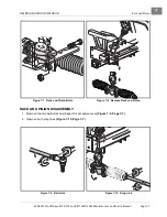
1. Chock the rear wheels, release the park brake, loosen the front wheel lug nuts and lift the front of the
vehicle with a chain hoist or floor jack.
See WARNING “lift only one end...” in
2. Place jack stands under the outer front frame I-beams and lower onto stands.
3. Remove the lug nuts from the front wheels.
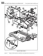
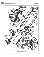
4. Remove the cotter pins (18) and ball joint retaining nuts (24)
5. Remove the ball joints (23) from the spindle assemblies.
6. Remove the four bolts (20), washers (21) and nuts (22) from the steering rack and pinion assembly
mounting bracket
.
Also see
7. Remove the bolt (27) and lockwasher
from the universal joint, then remove the
rack and pinion assembly and universal joint from the vehicle
.
Summary of Contents for CARRYALL 272
Page 2: ......
Page 14: ......
Page 18: ...1...
Page 52: ...5...
Page 90: ...6...
Page 110: ...7...
Page 112: ...8...
Page 128: ...10...
Page 170: ...11...
Page 224: ...13...
Page 284: ...16...
Page 302: ...17...
Page 308: ......
Page 309: ...Club Car R NOTES...
Page 310: ...Club Car R NOTES...
Page 311: ......

