ELECTRICAL COMPONENTS: FE400, KEY-START ENGINE
Starter/Generator (Model G425419)
2006-2010 Turf/Carryall 272/472 and XRT 1200/1200 SE Maintenance and Service Manual
Page 12-3
12
Brush Spring Inspection and Replacement
1. Visually inspect springs. Replace all four springs if any spring is discolored from heat (straw or bluish in
color).
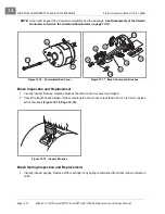
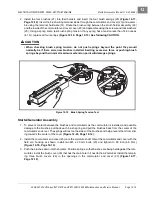
2. Install the four brushes (27) into their holders and insert the four brush springs (28)
. Using a spring scale, test brush spring tension. If any spring has a tension less than 24
ounces (6.67 N), replace all four springs
.
See following CAUTION.
CAUT ION
• When checking brush spring tension, do not push springs beyond the point they would
normally be if there were new brushes installed. Exerting excessive force or pushing brush
springs beyond their normal maximum extension point will damage springs.
Starter/Generator Assembly
1. Connect the brush wires to the holders using four lockwashers (26) and four screws (25). Make sure the
crossover leads are also connected. Tighten the screws to 31 in-lb (3.5 N·m)
.
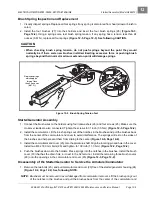
2. Install the commutator. Lift the brush springs out of the notches in the brushes and pull the brushes back
from the center of the commutator end cover to avoid interference. The springs will rest on the sides of
the brushes and help prevent them from sliding to the center
.
3. Install the commutator end cover (23) onto the armature shaft. Align the locating pin and hole in the cover.
Install two M6 x 180 mm bolts (20) and tighten to 100 in-lb (11.3 N·m)
4. Push the brushes down into the holders. Place springs into the notches in the brushes. Install the brush
cover (30) that has the drain hole in it next to the A2 terminal. Install the remaining three brush covers
(29) onto the openings in the commutator end cover (23)
Disassembly of the Starter/Generator to Service the Armature/Commutator
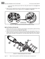
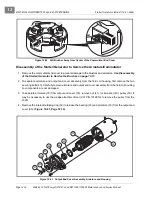
1. Remove the two bolts (20), and pull commutator end cover (23) free of the starter/generator housing (24)
.
See following NOTE.
NOTE:
Brushes must be removed to avoid damaged from commutator removal. Lift the brush springs out
of the notches in the brushes and pull the brushes back from the center of the commutator and
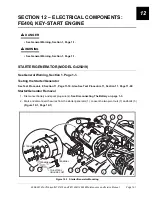
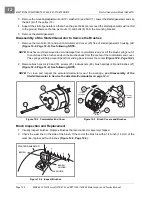
Figure 12-5 Brush Spring Tension Test
Replace springs
which apply a
force of less
than 24 ounces
(6.67 N).
0
5
10
15
20
25
30
35
40
45
50
Summary of Contents for CARRYALL 272
Page 2: ......
Page 14: ......
Page 18: ...1...
Page 52: ...5...
Page 90: ...6...
Page 110: ...7...
Page 112: ...8...
Page 128: ...10...
Page 170: ...11...
Page 224: ...13...
Page 284: ...16...
Page 302: ...17...
Page 308: ......
Page 309: ...Club Car R NOTES...
Page 310: ...Club Car R NOTES...
Page 311: ......

