


COPYRIGHT © 2001 CANON INC.
2000 2000 2000 2000
CANON iR5000i/iR6000i REV.0 JUNE 2001
P7
CONTENTS
4.5.2
Removing the Lower Separation
Claw ................................. 6-35P
4.6
Delivery Assembly ................. 6-36P
4.6.1
Removing the External Delivery
Roller ............................... 6-36P
4.6.2
Removing the Internal Delivery
Roller ............................... 6-37P
4.6.3
Adjusting the Position of the
Delivery Flapper Solenoid
(SL5) ................................ 6-38P
4.7
Paper Sensor .......................... 6-39P
4.7.1
Removing the Claw Jam Sensor
......................................... 6-39P
4.7.2
Removing the Internal Delivery
Sensor .............................. 6-39P
4.7.3
Removing the Delivery Jam
Sensor .............................. 6-40P
4.7.4
Removing the External Delivery
Sensor .............................. 6-41P
4.8
Fixing Assembly Inlet Guide As-
sembly .................................... 6-42P
4.8.1
Adjusting the Position of the
Fixing Assembly Inlet Guide
Solenoid (SL1) ................ 6-42P
4.8.2
Adjusting the Position of the
Fixing Assembly Inlet Guide
......................................... 6-42P
CHAPTER 7 EXTERNALS AND CONTROLS
1. Control Panel .................................. 7-1P
1.1
Outline ..................................... 7-1P
2. Fans ................................................ 7-2P
2.1
Arrangement, Functions, and Error
Codes ....................................... 7-2P
2.2
Operation ................................. 7-4P
2.2.1
Controlling the Speed ........ 7-4P
2.2.2
Sequence of Operations ..... 7-4P
3. Power Supply ................................. 7-5P
3.1
Power Supply ........................... 7-5P
3.1.1
Outline ............................... 7-5P
3.1.2
Distribution of Power Among
Switches ............................. 7-6P
3.1.3
Output of Power Supplies
........................................... 7-8P
3.2
Rated Outputs of the DC Power
Supply ...................................... 7-9P
3.3
Protection Mechanism ........... 7-10P
4. Others ........................................... 7-12P
4.1
Silent Mode ............................ 7-12P
5. Disassembly and Assembly .......... 7-13P
5.1.1
External Covers ............... 7-14P
5.1.2
Removing the Front Cover
......................................... 7-15P
5.1.3
Removing the Top Plate
......................................... 7-15P
5.2
Arrangement of Electrical Parts
(rear of the machine) .............. 7-16P
5.3
Control Panel ......................... 7-18P
5.3.1
Removing the Control Panel
......................................... 7-18P
5.3.2
Removing the LCD Panel
......................................... 7-19P
5.3.3
Removing the Control Panel In-
verter PCB ....................... 7-20P
5.3.4
Removing the Control Panel
Family PCB ..................... 7-21P
5.4
PCBs ...................................... 7-22P
5.4.1
DC Controller PCB ......... 7-22P
5.4.2
Removing the Main Controller
Box .................................. 7-23P
5.4.3
Removing the Ethernet PCB
......................................... 7-26P
5.4.4
Removing the Main Controller
PCB .................................. 7-26P
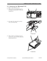
5.4.5
Remove the Differential PCB
......................................... 7-27P
5.4.6
Removing the LIPS PCB
......................................... 7-27P
5.4.7
Removing the RISER PCB
......................................... 7-28P


