


COPYRIGHT © 2001 CANON INC.
2000 2000 2000 2000
CANON iR5000i/iR6000i REV.0 JUNE 2001
CHAPTER 5 SERVICE MODE
5-36 T
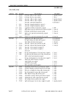
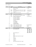
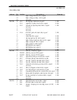
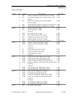
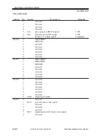
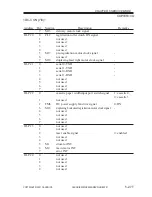
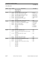
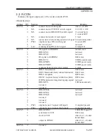
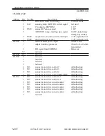
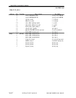
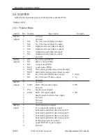
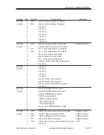
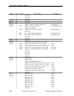
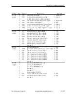
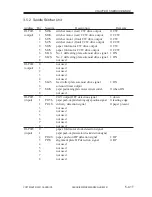
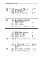
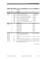
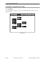
3.5 SORTER
Indicates the input/output ports of the finisher controller PCB.
<Sorter (1/3)>
3.5.1 Finisher Block
Address
IO-P001
(output)
IO-P002
(output)
IO-P003
(output)
IO-P004
(input)
Bit
0
1
2
3
4
5
6
7
8
0
1
2
3
4
5
6
7
8
0
1
2
3
4
5
6
7
8
0
1
2
3
4
5
6
7
8
Notation
M8
M8
M4
M4
M3
M3
M5
M2
M7
M1P
M2P
M2P
M5
M5
LED2
PS1
LED1
Description
not used
not used
No. 2 feed motor phase A output
No. 2 feed motor phase B output
stapler shift motor phase B output
stapler shift motor phase A output
alignment motor phase B output
alignment motor phase A output
not used
tray lift motor PWM
delivery motor PWM
swing motor PWM
punch motor PWM
horizontal registration motor phase B output
horizontal registration motor phase A output
tray lift motor DOWN drive output
tray lift motor UP drive output
not used
not used
LED2 ON solenoid output
not used
height sensor (input)
LED1 ON signal output
height sensor external clock (input)
not used
not used
not used
dust full detection signal
24-V output off detection signal
horizontal registration detection signal 1
horizontal registration detection signal 2
horizontal registration detection signal 3
horizontal registration detection signal 4
trailing edge detection signal
punch LED ON signal (output)
not used
Remarks
1: down
1: up
0: ON
1: ON


