COPYRIGHT © 2001 CANON INC.
2000 2000 2000 2000
CANON iR5000i/iR6000i REV.0 JUNE 2001
CHAPTER 2 MAIN CONTROLLER
2-9 S
2.2 Input Image Processing
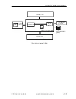
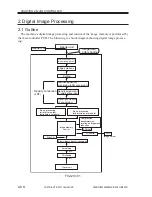
The input image data from the reader unit is processed as follows:
2.2.1 Image Data from the Reader Unit
The image data from the reader unit is 8-bit, 256-gradation luminance signals which have
been subjected to shading correction.
Further, the input is from two signal lines (odd-/even-number pixels).
2.2.2 Enlargement/Reduction (main scanning direction)
An image is enlarged/reduced by processing image data when writing it to the image
memory or reading it from the image memory.
2.2.3 Edge Emphasis
Edge emphasis is performed to enhance the crispness of text, text/photo, film photo, and
print photo modes while reducing moire as much as possible.
2.2.4 Editing
The machine’s editing functions include the following: blanking/framing, negative/posi-
tive reversal, slant, mirror, fold, repeat.
2.2.5 Density Conversion (LUT)
In this block, luminance image signals are converted into density image signals, and pro-
cessing is performed so that the output density curve best suited to each mode may be ob-
tained.
a. LOG Conversion
A LOG conversion table is used to convert luminance image signals possessing lumi-
nance data based on reflected light into density image signals possessing density data of
toner.
b. Density Adjustment (F-value conversion)
An F-value table suited to the setting of the Copy Density key on the control panel is
used to perform density adjustment. It, however, is not performed in memory copy mode.
c. Density Correction (
ϒ
conversion)
The
ϒ
conversion table for text, text photo, film photo, or print photo is used to perform
density correction.
2.2.6 Binary Processing (error diffusion; T-BIC)
The machine’s error diffusion method (T-BIC) ensures the best binary processing by con-
trolling texture for best printing results. The 8-bit image density signal of text, text/photo, or
print photo mode is converted into a 1-bit image density signal (binary).

