COPYRIGHT © 2001 CANON INC.
2000 2000 2000 2000
CANON iR5000i/iR6000i REV.0 JUNE 2001
CHAPTER 7 EXTERNALS AND CONTROLS
7-39 P
[1]
[2]
[1]
[1]
[3]
[2]
[1]
To transformer
[1]
[1]
[1]
[3]
[2]
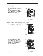
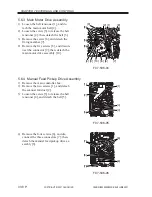
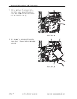
5.6.5 Waste Toner Drive Assembly
1) Remove the DC controller base.
2) Remove the flywheel, and loosen the
belt tensioner to detach the main motor
belt.
3) Remove the waste toner bottle holder.
4) Remove the three screws [1], and detach
the waste toner drive assembly [2].
F07-506-07
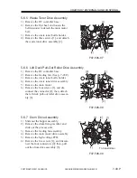
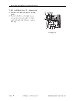
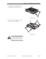
5.6.6 Left Deck Pull-Out Roller Drive Assembly
1) Remove the DC controller base.
2) Remove the feeding fan. (See p. 7-28P.)
3) Remove the waste toner bottle holder.
4) Remove the waste toner drive assembly.
5) Remove the main motor.
6) Remove the four screws [1], and dis-
connect the connector [2]; then, detach
the left deck pull-out roller drive assem-
bly [3].
F07-506-08
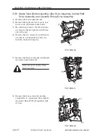
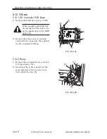
5.6.7 Drum Drive Assembly
1) Slide out the hopper assembly.
2) Remove the drum fixing member, and
slide out the process unit.
3) Remove the feeding fan assembly.
4) Remove the main motor drive assembly.
5) Remove the high-voltage PCB.
6) Remove the five screws [1], and discon-
nect the four connectors [2]; then, pull
out the drum drive assembly [3].
F07-506-09

