COPYRIGHT © 2001 CANON INC.
2000 2000 2000 2000
CANON iR5000i/iR6000i REV.0 JUNE 2001
CHAPTER 7 EXTERNALS AND CONTROLS
7-31 P
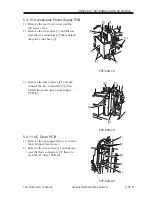
5.4.10 Accessories Power Supply PCB
1) Remove the rear lower cover and the
left lower cover.
2) Remove the six screws [1], and discon-
nect the six connectors [2]; then, detach
the power cord base [3].
F07-504-18
3) Remove the three screws [4], and dis-
connect the two connectors [5]; then,
detach the accessories power supply
PCB [6].
F07-504-19
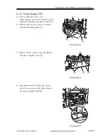
5.4.11 AC Driver PCB
1) Remove the rear upper/lower cover and
the left upper/lower cover.
2) Remove the two screws [1], and discon-
nect the three connectors [2]; then, de-
tach the AC driver PCB [3].
F07-504-20
[1]
[2]
[1]
[1]
[1]
[3]
[2]
[4]
[5]
[4]
[6]
[1]
[2]
[3]
[2]
[1]

