COPYRIGHT © 2001 CANON INC.
2000 2000 2000 2000
CANON iR5000i/iR6000i REV.0 JUNE 2001
CHAPTER 8 PAPER DECK
8-15 P
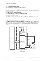
1.6.2 Controlling the Deck Lifter Motor (M102)
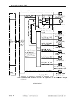
The deck lifter motor control circuit is located on the deck driver PCB. (See F08-106-02
for its block diagram.)
The combination circuit shown in the figure consists of various logic circuits, and serves
to drive the deck lifter motor clockwise or counterclockwise based on the combination of
the output signals form the various sensors, deck lifter motor drive signal (DLMON*) from
the DC controller of the host machine, and deck lifter UP signal (DLUP*).
If the deck lifter position sensor (PS104) does not detect the lifter within a specific period
of time in the presence of the deck lifter UP signal, the machine will indicate an error code
('05'; may be checked in service mode COPIER>DISPLAY>ALARM1>BODY).
[1] Conditions for Moving Up the Lifter
•
The lifter is connected to its host machine; i.e., the deck set signal (DSET) is ‘1’.
•
The compartment is closed; i.e., the deck open detection signal (DOPND*) is ‘1’.
•
The compartment is closed; i.e., the deck open detecting switch is ON.
•
The deck lifter upper limit detection signal (DLUL) is ‘0’ and, in addition, the deck
lifter position detection signal (DLPD) is ‘0’.
•
The deck lifter motor drive signal (DLMON*) is ‘0’.
•
The deck lifter UP signal (DLUP*) is ‘0’.
The above conditions will cause the lifter to move up.
[2] Conditions for Moving Down the Lifter
•
The lifter is open; i.e., the deck open detection signal (DOPND*) is ‘0’.
•
The deck lifter lower limit detection signal (DLLD) is ‘0’ and, in addition, the deck lifter
position detection signal (DLPD) is ‘0’.
•
The deck lifter motor drive signal (DLMON*) is ‘0’.
•
The deck UP signal (DLUP*) is ‘1’.
The above conditions cause the lifter to move down.

