COPYRIGHT © 2001 CANON INC.
2000 2000 2000 2000
CANON iR5000i/iR6000i REV.0 JUNE 2001
CHAPTER 4 TROUBLESHOOTING IMAGE FAULTS/MALFUNCTIONS
4-34 T
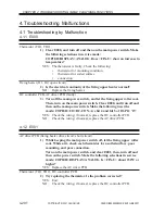
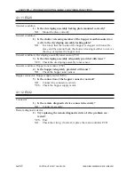
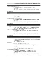
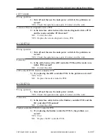
4.1.34 E717
Connector
1) Is the remote diagnostic device PCB connected securely?
NO:
Connect it securely.
Remote diagnostic device PCB, Main controller PCB
2) Try replacing the remote diagnostic device PCB. Is the problem
corrected?
YES: End.
NO:
Replace the main controller PCB.
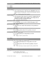
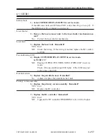
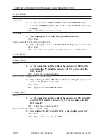
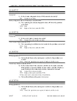
4.1.35 E719
Connector
1) Is the coin vendor connected securely?
NO:
Connect the coin vendor securely.
Coin vendor, Main controller PCB
2) Try connecting to a different coin vendor. Is the problem corrected?
YES: End.
NO:
Replace the main controller PCB.
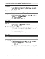
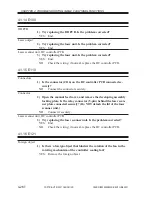
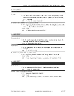
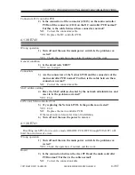
4.1.36 E732
Wrong operation
1) Turn off and then on the main power switch. Is the problem cor-
rected?
YES: Check the operation once again; if normal, end the work.
Connectors, Reader controller PCB
2) Is the connection of the connector (J1014) on the main controller
PCB and the connector (J5004) on the reader controller PCB nor-
mal? Further, is the cable between these connectors normal?
NO:
Correct the connectors/cable.
YES: Replace the reader controller PCB.
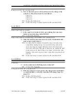
If the reader unit is detected at time of installation,
3) Turn off and then on the power to recover.
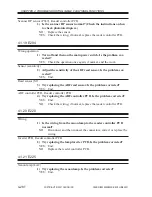
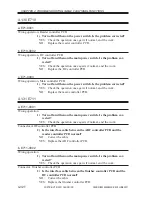
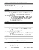
4.1.37 E733
Wrong operation
1) Turn off and then on the main power switch. Is the problem cor-
rected?
YES: Check the operation once again; if normal, end the work.

