


COPYRIGHT © 2001 CANON INC.
2000 2000 2000 2000
CANON iR5000i/iR6000i REV.0 JUNE 2001
CHAPTER 7 EXTERNALS AND CONTROLS
7-5 P
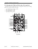
3. Power Supply
3.1 Power Supply
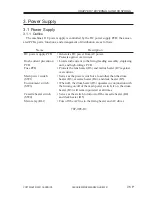
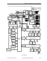
3.1.1 Outline
The machine’s DC power supply is controlled by the DC power supply PCB; the associ-
ated PCBs, parts, functions, and arrangement of distribution are as follows:
T07-301-01
Name
DC power supply PCB
Rush current prevention
PCB
Fuse PCB
Main power switch
(SW1)
Environment switch
(SW3)
Cassette heater switch
(SW4)
Main relay (RL1)
Description
• Generates DC power from AC power.
• Protects against overcurrent.
• Limits rush current to the fixing/feeding assembly, duplexing
unit, and high-voltage PCB.
• Protects the lens heater (H6) and mirror heater (H7) against
overcurrent.
• Serves as the power switch of a load other than the drum
heater (H3), cassette heater (H4), and deck heater (H5).
• When off, the drum heater (H3) operates in conjunction with
the turning on/off of the main power switch; if on, the drum
heater (H3) will remain powered at all times.
• Serves as the switch to turn on/off the cassette heater (H4)
and deck heater (H5).
• Cuts off the AC line to the fixing heater and AC driver.