COPYRIGHT © 2001 CANON INC.
2000 2000 2000 2000
CANON iR5000i/iR6000i REV.0 JUNE 2001
CHAPTER 1 BASIC OPERATION
1-5 R
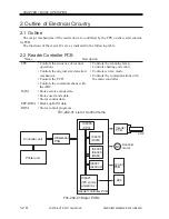
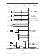
4.2 Inputs to and Outputs from the Reader Controller PCB
• Inputs to and Outputs from the Reader Controller PCB (1/2)
+5V
Scanner HP
sensor
PS39
J5012
-3
-2
-1
J5057
-1
-2
-3
HPSENS
J5052
-6
-5
-4
-3
-2
-1
+5V
Copyboard
cover sensor
PS40
J5012
-6
-5
-4
J5056
-1
-2
-3
ADF_OPEN*
J5051
-1
-2
-3
-6
-5
-4
When the scanner is in
home position, '1'.
When the copyboard
cover is closed, '1'.
When the reader controller PCB is ON,
24: ON --> heater: OFF
When the reader controller PCB is OFF,
24V: OFF --> heater: ON
+5V
Original sensor
PS43
J5006
-1
-2
-3
D_SENS3*
J5053
-3
-2
-1
-1
-2
-3
When paper is detected,
'1'.
+24V
Scanner motor
J5011
-6
-5
-4
-3
-2
-1
B*
B
A*
A
M3
Rotates in response to
alternating '1' and '0'.
(pulse signal)
Inverter
PCB
J5102
-1
-4
J5101
-1
-3
-4
-2
J5007
-5
-3
-2
-4
J5062
-1
-3
-4
-5
-5
-3
-2
-1
+24V
+24V
LAMP_ON
INV_ERR
Reader controller PCB
CCD/AP
PCB
J6001
-1
-2
-3
-4
J5002
-1
-2
-3
-4
A12V
GND
GND
A5V
Fuse PCB
J5601
J5001
J6002
J5003
See Chapter 3
"Controlling the CCD."
LA2
Scanning
lamp
Mirror heater
CCD
H7
H6
Lens heater
J5100
-1
-2
-1
-2
J5603
-1
-2
J5602
-1
-2
J5101
-1
-3
-3
-1
-1
-2
AC inlet
AC100V
See Chapter 2
"Controlling the
Scanning Lamp."
100-V model only
( only at time of detection )
F01-402-01

