COPYRIGHT © 2001 CANON INC.
2000 2000 2000 2000
CANON iR5000i/iR6000i REV.0 JUNE 2001
CHAPTER 4 TROUBLESHOOTING IMAGE FAULTS/MALFUNCTIONS
4-35 T
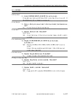
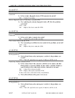
Connectors, DC controller PCB
2) Is the connection of the connector (J1015) on the main controller
PCB and the connector (J122) on the DC controller PCB normal?
Further, is the cable between these connectors normal?
NO:
Correct the connectors/cable.
YES: Replace the DC controller PCB.
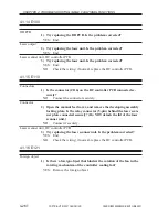
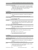
4.1.38 E740
Wrong operation
1) Turn off and then on the main power switch. Is the problem cor-
rected?
YES: Check the operation once again; if normal, end the work.
General condition
2) Is the detail code ‘0002’?
YES: Go to step 4.
Connectors
3) Are the connectors of the Network PCB and the connectors of the
main controller PCB normal? Further, is the cable between these
connectors normal?
NO:
Correct the connectors/cable.
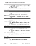
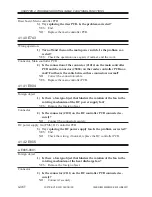
MAC address setting
4) Have the MAC address checked by the network administrator, and
reset it. Is the problem corrected?
YES: End.
LAN card, Main controller PCB
5) Try replacing the Network PCB. Is the problem corrected?
YES: End.
NO:
Replace the main controller PCB.
If the reader unit is detected at time of installation,
6) Turn off and then on the power to recover.
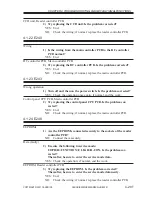
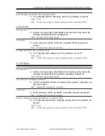
4.1.39 E741
Disabling each PCI slot in service mode (BOARD>PCI1-OFF through PCI3-OFF) will
limit the occurrence of errors.
Wrong operation
1) Turn off and then on the main power switch. Is the problem cor-
rected?
YES: Check the operation; if normal, end the work.
Board
2) Is the connection between the riser PCB and the main controller
PCB normal? Further, is the cable normal?
NO:
Correct the connection/cable.

