COPYRIGHT © 2001 CANON INC.
2000 2000 2000 2000
CANON iR5000i/iR6000i REV.0 JUNE 2001
CHAPTER 2 SEQUENCE OF OPERATIONS
2-14 P
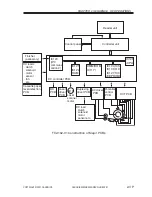
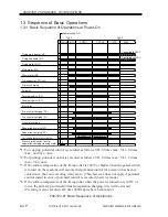
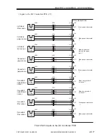
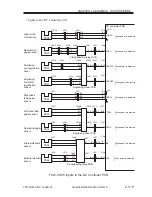
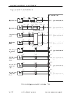
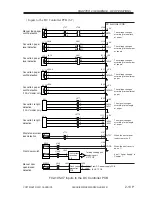
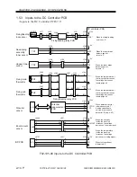
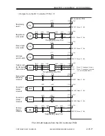
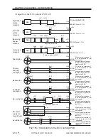
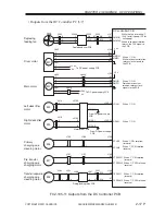
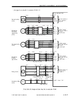
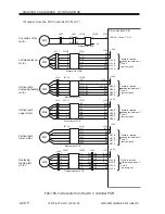
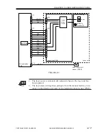
1.5.3 Inputs to the DC Controller PCB
• Inputs to the DC Controller PCB (7/7)
F02-105-08 Inputs to the DC Controller PCB
+24V
DC controller PCB
Developing
assembly
toner sensor
+5V
+12V
Hopper toner
sensor
J103
-B9
-B10
-B11
TEP
When the toner drops
below a specific
volume, '0'.
J153
-3
-2
-1
-5
-6
-7
TS2
+5V
J103
-A7
-A8
-A9
DTEP
FFUS*
When the toner drops
below a specific
volume, '0'.
TS1
J265
-3
-1
-1
-3
TH1
TH2
J267
-2
-1
-1
-2
J253
-5
-3
-6
-8
J251
-B14
-B13
-B7
-B8
J106
-B7
-B8
TH1
TH2
-2
-1
-9
-10
-12
-11
-B9
-B10
-14
-13
-B6
-B8
-B12
-B11
-B9
-B10
J106
-B9
-B10
VS1
POTON
POT
J103
-B1
-B2
-B3
-B4
When potential control
is being executed, '1'.
Analog correction to
suit the drum surface
potential. (See p. 4-5P.)
HUM1
+5V
HUM OUT
TH
J113
-A11
-A10
-A9
-A8
-A7
J8492
-1
-2
-3
-4
-5
J801
-A11
-A10
-A9
-A8
-A7
-A5
-A6
-A7
-A8
-A9
When the humidity
inside the machine
increases, the voltage
decreases. (analog signal)
When the temperature
inside the machine
increases, the voltage
decreases. (analog signal)
When the temperature of
the fixing roller increases,
the voltage decreases.
(analog signal)
When the temperature of
the fixing roller increases,
the voltage decreases.
(analog signal)
J162
-3
-2
-1
-1
-2
-3
J156
-3
-2
-1
-1
-2
-3
N.O.
MSW3
Fixing/feeding
lock sensor
J106
-A12
-A1
J271
-3
-1
-1
-3
J252
-3
-1
-11
-13
J251
-A9
-A20
-A12
-A1
When the fixing/feeding
unit is set, '0'.
J281
J283
-3
-14
-11
-13
Fixing/feeding relay PCB
J287
J282
Fixing/feeding relay PCB
Fixing main
thermistor
Fixing sub
thermistor
Potential
sensor
Environment
sensor
Potential
measurement
PCB
BD PCB
BD
+5V
BD*
J120
-1
-2
-3
J2701
-4
-3
-2
-1
J401
-1
-2
-3
-4
-4
-3
-2
When the laser beam
is detected, '0'.

