


COPYRIGHT © 2001 CANON INC.
2000 2000 2000 2000
CANON iR5000i/iR6000i REV.0 JUNE 2001
CHAPTER 5 PICK-UP/FEEDING SYSTEM
5-4 P
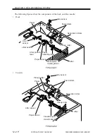
2. Pickup Assembly
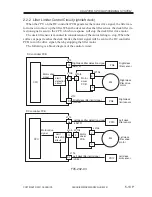
2.1 Pickup Control System
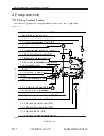
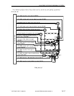
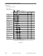
The following figure shows the system used to control deck pickup operations:
F05-201-01
F05-201-01
M4
M5
DC controller PCB
PS32
PS7
PS6
SL7
SL6
PS10
PS19
PS24
PS29
PS20
PS11
PS28
M17
M25
M11
M12
CL2
J113-A5 Vertical path paper detection signal (VP1PD)
J104B Pre-registration motor drive signal
J113-B2 Laser write start detection signal (LWRPD)
J106-A9 Registration paper detection signal (RGPD)
J108A Main motor drive signal
J106-A6 Registration roller clutch drive signal (RGCD*)
J104-B Vertical path duplexing motor drive signal
J115-B13 Left deck pull-out clutch signal (LDCLD*)
J107-A16 Left deck feed paper detection signal (LDPFS)
J104A Left deck pickup motor
J102-B6 Left deck pickup solenoid drive signal
(LDPUSD*)
J115-11A Left deck retry signal (LDRT)
J115-A5 Left deck lifter detection signal
(LDLTP)
J115-A8 Left deck paper detection signal
(LDPD)
J105-12 Left deck lifter drive signal (LDLM)
J105-3 Right deck pickup solenoid drive signal (RDPUSD*)
J104A Right deck pickup motor drive signal
J112-A2 Right deck lifter detection signal (RDLTP)
J112-A5 Right deck paper detection signal (RDPD)
J105-13 Right deck lifter motor drive signal (RDLM)
J112-A8 Right deck retry signal (RDRT)
J112-B5 Right deck feed paper detection signal (RDPFS)
CL4
M2
PS33


