COPYRIGHT © 2001 CANON INC.
2000 2000 2000 2000
CANON iR5000i/iR6000i REV.0 JUNE 2001
CHAPTER 1 MAINTENANCE AND INSPECTION
1-8 T
8. Clean each filter by removing matter adhering to its surface: 1. ozone filter, 2. dust-
proofing filter.
9. Clean the developing assembly (developing assembly rolls).
10. Clean the pickup/feeding assembly: 1. transfer guide (upper/lower) plate, 2. registration
roller (upper, lower), 3. feeding belt, 4. each feeding roller.
11. Clean the fixing/delivery assembly: 1. separation law (upper, lower), 2. each feeding
roller, 3. inlet guide, 4. web (check), 5. inlet guide oil dish, 6. thermistor, 7. sub ther-
mistor, 8. thermal switch.
12. Clean the cleaning assembly (side scraper).
13. Clean the copyboard glass and the reading glass.
14. Make test prints.
15. Make sample prints.
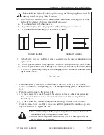
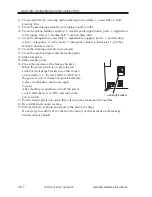
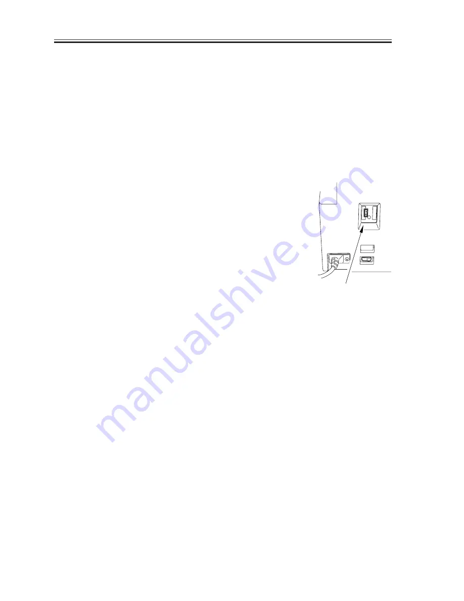
16. Check the operation of the leakage breaker:
While the power switch is on, press the test
switch of the leakage breaker to see that it oper-
ates normally (i.e., the lever shifts to ‘OFF’ and
the power is cut). If it does not operate normally,
replace it and make a check once again.
To reset,
After checking its operation, turn off the power
switch, shift the lever to ‘ON’, and turn on the
power switch.
17. Put the sample prints into order; then, clean up the area around the machine.
18. Record the final counter reading.
19. Fill out the Service Book, and report to the person in charge.
Do not forget to add the above check to the history of checks made on the leakage
breaker (Service Book).
Leakage breaker


