COPYRIGHT © 2001 CANON INC.
2000 2000 2000 2000
CANON iR5000i/iR6000i REV.0 JUNE 2001
CHAPTER 4 TROUBLESHOOTING IMAGE FAULTS/MALFUNCTIONS
4-45 T
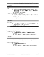
Wiring, Connector
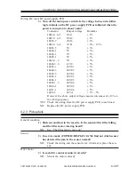
3) Are the connection and the wiring of the connectors from J5004 on
the reader controller PCB to J1014 on the main controller PCB
normal?
NO:
Correct the wiring, and connect the connectors securely.
Scanner motor (M3), Reader controller PCB
4) Try replacing the Scanner motor. Is the problem corrected?
YES: End.
NO:
Replace the reader controller PCB.
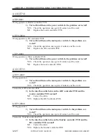
4.2.10 The pre-exposure LED fails to turn on
Pre-exposure LED (LA1)
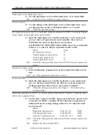
1) Press the Start key. Does the state of bit 4 in service mode
(COPIER>I/O>DC-CON>IO-P15) change from ‘0’ to ‘1’?
YES: Check the wiring from the DC controller PCB to the pre-exposure
LED; if normal, replace the pre-exposure LED.
Pre-exposure LED (LA1), DC controller PCB
2) Set the meter range to 30 VDC. Does the voltage between J103-A3
(+) and J103-A4 (GND) on the DC controller PCB change from 0 to
24 V?
YES: Check the wiring from the DC controller PCB to the pre-exposure
LED; if normal, replace the pre-exposure LED.
NO:
Replace the DC controller PCB.
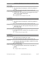
4.2.11 The scanning lamp fails to turn on
Lamp (mounting)
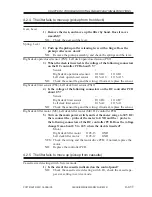
1) Is the scanning lamp mounted correctly?
NO:
Disconnect the power plug from the power outlet, and mount the
lamp correctly.
Reader controller PCB
2) Press the Start key. Does bit 7 in service mode (COPIER>I/O>R-
CON>IO-P1) change from ‘1’ to ‘0’?
NO:
Replace the reader controller PCB.
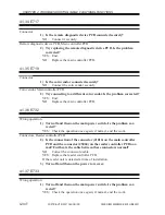
Inverter PCB
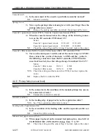
3) Try replacing the inverter PCB. Is the problem corrected?
YES: End.
Scanning lamp (LA2), Reader controller PCB
4) Try replacing the scanning lamp. Is the problem corrected?
YES: End.
NO:
Replace the reader controller PCB.

