COPYRIGHT © 2001 CANON INC.
2000 2000 2000 2000
CANON iR5000i/iR6000i REV.0 JUNE 2001
CHAPTER 4 TROUBLESHOOTING IMAGE FAULTS/MALFUNCTIONS
4-29 T
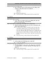
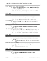
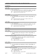
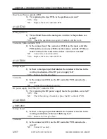
CCD unit, Reader controller PCB
2) Try replacing the CCD unit. Is the problem corrected?
YES: End.
NO:
Check the wiring; if normal, replace the reader controller PCB.
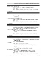
4.1.22 E240
Wiring
1) Is the wiring from the main controller PCB to the DC controller
PCB normal?
YES: End.
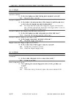
DC controller PCB, Main controller PCB
2) Try replacing the DC controller PCB. Is the problem corrected?
YES: End.
NO:
Check the wiring; if normal, replace the main controller PCB.
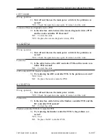
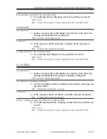
4.1.23 E243
Wrong operation
1) Turn off and then on the power switch. Is the problem corrected?
YES: Check the operation once again; if normal, end the work.
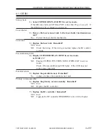
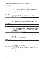
Control panel CPU PCB, Main controller PCB
2) Try replacing the control panel CPU PCB. Is the problem cor-
rected?
YES: End.
NO:
Check the wiring; if normal, replace the main controller PCB.
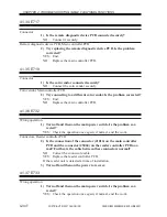
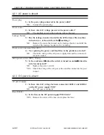
4.1.24 E248
EEPROMs
1) Are the EEPROMs connected securely to the sockets of the reader
controller PCB?
NO:
Connect them securely.
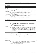
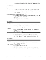
Data (faulty)
2) Execute the following in service mode:
COPIER>FUNCTION>CLEAR>R-CON. Is the problem cor-
rected?
Thereafter, be sure to enter the service mode data.
YES: Check the operation; if normal, end the work.
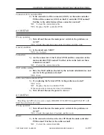
EEPROM, Reader controller PCB
3) Try replacing the EEPROM. Is the problem corrected?
Thereafter, be sure to enter the service mode data newly.
YES: End.
NO:
Check the wiring; if normal, replace the reader controller PCB.

