


Chapter 14
14-43
F-14-105
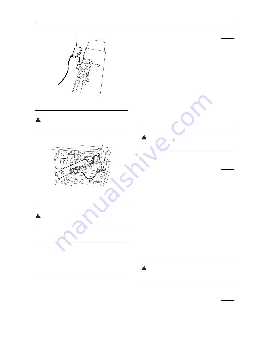
8) Connect the cable [1] of the potential sensor checking electrode to the
frame (GND) [2] of the machine.
Be sure to allow enough space from the sensor window so that the clip
will never come into contact with the sensor cover.
F-14-106
9) Fit the door switch actuator into the door switch assembly.
10) Turn on the power switch.
After turning on the power switch, do not touch the potential sensor
assembly.
11) Make the following selections in service mode, and check to see that
the reading for initial rotation is between 0 and 30:
COPIER>DISPLAY>DPOT>DPOT-K.
REF:
1. If the reading in method 1 is as indicated but the reading in method 2
is not as indicated,
Suspect dirt on the sensor or a fault in the potential measurement unit.
2. If the readings in both methods 1 and 2 are as indicated,
It is safe to assume that the operation and the signal path from the
potential sensor unit to the microprocessor on the DC controller PCB are
normal.
12) Turn off the power switch.
13) Detach the potential sensor checking electrode.
14) Mount the potential sensor support plate.
15) Turn on the power switch.
14.7.18 Checking the Environment Sensor
0007-0793
iR105i/iR105+ / iR9070
1) Checking the Environment Sensor
Make the following selections in service mode, and check and record
the temperature/ humidity indicated on the screen in the control
panel: COPIER> DISPLAY> ANALOG.
Data A
'RTMP' deg C ........... data A1
'RHUM' % ........... data A2
2) Press the Rest key twice to turn off the power switch.
3) Remove the environment sensor, and fit the environment sensor jig
(FY9-3014) in its place.
4) Turn on the power switch, and leave the machine alone for 5 min.
5) Make the following selections in service mode, and check and record
the temperature/ humidity indicated on the screen in the control
panel: COPIER> DISPLAY> ANALOG:
Data B
'RTMP' deg C ........... data B1
'RHUM' % ........... data B2
6) Compare data A and data B.
- difference between data A 1 and data B1 is 0 -/+ 5
- difference between data A2 and data B2 is 0 -/+ 20
If the difference between data A and data B is outside the range, replace
the environment sensor.
7) Press the Reset key twice, and turn off the power switch.
8) Detach the environment sensor jig, and fit the environment sensor.
9) Put back all covers.
The environment sensor jig (FY9-3014) is precisely adjusted at the
factory.
Be sure to keep it in an air-tight case with a drying agent.
14.7.19 Checking the Environment Sensor
0008-8545
/ iR85+ / iR8070
1) Make the following selections in service mode:
COPIER>DISPLAY>ANALOG. Then,
check and record the temperature and humidity readings on the control
panel display.
(data A)
'RTMP' deg C ....... data A1
'RHUM' % ....... data A2
2) Press the Reset key twice, and turn offf the power switch.
3) Remove the environment sensor, and fit the environment sensor jig
(FY9-3014) in place.
4) Turn on the power switch, and leave the machine alone for 5 min.
5) Make the following selections in service mode:
COPIER>DISPLAY>ANALOG. Then, check and record the
temperature and humidity readings on the control panel display.
(data B)
'RTMP' deg C ....... data B1
'RHUM' % ....... data B2
6) Compare data A and data B.
- The difference between data A1 and data B1 is 0 ±5.
- The difference between data A2 and data B2 is 0 ±20.
If the difference between data A and data B is not as indicated, replace
the environment sensor.
7) Press the Reset key twice, and turn offf the power switch.
8) Detach the environment sensor jig, and fit the environment sensor.
9) Attach all covers.
The environment sensor jig (FY9-3014) is adjusted at the factory to a
high level of accuracy. Be sure to put it in a sealed case with a drying
agent for storage.
14.7.20 Checking the Photointerrupters
0007-0796
iR105i/iR105+ / iR9070
[1]
[2]
[1]
[2]
Summary of Contents for ImageRunner iR8500 Series
Page 1: ...Apr 5 2005 Service Manual iR8500 Series ...
Page 2: ......
Page 6: ......
Page 32: ...Contents ...
Page 33: ...Chapter 1 Introduction ...
Page 34: ......
Page 98: ......
Page 99: ...Chapter 2 Installation ...
Page 100: ......
Page 180: ...Chapter 2 2 78 F 2 272 2 1 1 3 ...
Page 181: ...Chapter 3 Basic Operation ...
Page 182: ......
Page 184: ......
Page 207: ...Chapter 4 Main Controller ...
Page 208: ......
Page 245: ...Chapter 4 4 35 F 4 72 1 2 ...
Page 246: ......
Page 247: ...Chapter 5 Original Exposure System ...
Page 248: ......
Page 252: ......
Page 306: ......
Page 307: ...Chapter 6 Image Processing System ...
Page 308: ......
Page 310: ......
Page 319: ...Chapter 7 Laser Exposure ...
Page 320: ......
Page 322: ......
Page 335: ...Chapter 8 Image Formation ...
Page 336: ......
Page 340: ......
Page 399: ...Chapter 9 Pickup Feeding System ...
Page 400: ......
Page 404: ......
Page 482: ......
Page 483: ...Chapter 10 Fixing System ...
Page 484: ......
Page 524: ......
Page 525: ...Chapter 11 External and Controls ...
Page 526: ......
Page 530: ......
Page 583: ...Chapter 12 MEAP ...
Page 584: ......
Page 586: ......
Page 589: ...Chapter 13 Maintenance and Inspection ...
Page 590: ......
Page 592: ......
Page 610: ...Chapter 13 13 18 F 13 17 1 2 3 ...
Page 648: ......
Page 649: ...Chapter 14 Standards and Adjustments ...
Page 650: ......
Page 654: ......
Page 723: ...Chapter 15 Correcting Faulty Images ...
Page 724: ......
Page 728: ......
Page 792: ......
Page 793: ...Chapter 16 Self Diagnosis ...
Page 794: ......
Page 796: ......
Page 841: ...Chapter 17 Service Mode ...
Page 842: ......
Page 1076: ......
Page 1077: ...Chapter 18 Upgrading ...
Page 1078: ......
Page 1080: ......
Page 1108: ...Chapter 18 18 28 F 18 45 3 Click Start F 18 46 4 Click Save F 18 47 5 Click OK ...
Page 1111: ...Chapter 19 Service Tools ...
Page 1112: ......
Page 1114: ......
Page 1120: ......
Page 1121: ...Apr 5 2005 ...
Page 1122: ......