Canon ImageRunner iR8500 Series Service Manual Download Page 685

Chapter 14

14-31

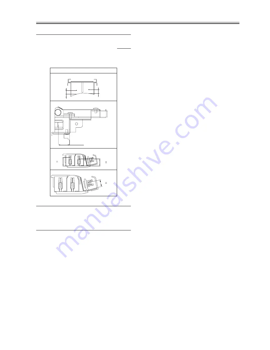
14.5 Image Formation System

14.5.1 Adjusting the Height of the Charging Wire

0008-8359

iR105i/iR105+ / iR9070 / iR85+ / iR8070

T-14-3

MEMO:

The height (position) of the primary and transfer charging wires may be

adjusted by turning the screw found at the rear of the charging assembly.

A full turn of the screw changes the position of the charging wire by

about 0.7 mm.

Height of charging wire

Primary

Pre-transfer

Separation

Transfer

7.5

- 0mm
+3mm

7.5

- 0mm
+3mm

13.6 ±0.3mm

No height adjusting 
mechanism

17.0

0.2mm

15.5

0.2mm

9.0

0.2mm

Summary of Contents for ImageRunner iR8500 Series

Page 1: ...Apr 5 2005 Service Manual iR8500 Series ...

Page 2: ......

Page 3: ... need arises In the event of major changes in the contents of this manual over a long or short period Canon will issue a new edition of this manual The following paragraph does not apply to any countries where such provisions are inconsistent with local law Trademarks The product names and company names used in this manual are the registered trademarks of the individual companies Copyright This ma...

Page 4: ...quiring care to avoid combustion fire Indicates an item prohibiting disassembly to avoid electric shocks or problems Indicates an item requiring disconnection of the power plug from the electric outlet Indicates an item intended to provide notes assisting the understanding of the topic in question Indicates an item of reference assisting the understanding of the topic in question Provides a descri...

Page 5: ...sed to indicate Low The voltage value however differs from circuit to circuit In addition the asterisk as in DRMD indicates that the DRMD signal goes on when 0 In practically all cases the internal mechanisms of a microprocessor cannot be checked in the field Therefore the operations of the microprocessors used in the machines are not discussed they are explained in terms of from sensors to the in...

Page 6: ......

Page 7: ... to Support Networking Requirements iR105 1 9 1 2 1 13 Support for MEAP Multifunctional Embedded Application Platform 1 9 1 2 2 Names of Parts 1 9 1 2 2 1 External View 1 9 1 2 2 2 External View 1 11 1 2 2 3 External View 1 11 1 2 2 4 Cross Section 1 13 1 2 2 5 Cross Section 1 14 1 2 2 6 Cross Section 1 15 1 2 2 7 External Covers 1 17 1 2 2 8 External Covers 1 19 1 2 2 9 External Covers 1 21 1 2 3...

Page 8: ...tallation 2 1 Making Pre Checks 2 1 2 1 1 Selecting the site 2 1 2 1 2 Selecting the site 2 2 2 1 3 Selecting the site 2 4 2 1 4 Selecting the site 2 6 2 1 5 Points to Note Before Starting the Work 2 8 2 1 6 Points to Note Before Starting the Work 2 8 2 1 7 Points to Note Before Starting the Installation Work 2 9 2 1 8 Points to Note Before Starting the Installation Work 2 9 2 1 9 Checking the Com...

Page 9: ... 2 42 Attaching the Labels Setting Paper Checking Images Operations and User Mode 2 46 2 2 43 Changing the Paper Size for the Front Deck right left 2 48 2 2 44 Changing the Paper Size for the Front Deck right left 2 48 2 2 45 Changing the Paper Size for the Front Deck right left 2 49 2 2 46 If Not Connected to a Network 2 49 2 2 47 If Not Connected to a Network 2 49 2 2 48 If Not Connected to a Ne...

Page 10: ... DC Controller PCB 3 6 3 8 3 1 10 Inputs to the DC Controller PCB 4 6 3 9 3 1 11 Inputs to the DC Controller PCB 5 6 3 10 3 1 12 Inputs to the DC Controller PCB 6 6 3 11 3 1 13 Outputs from the DC Controller PCB 1 7 3 12 3 1 14 Outputs from the DC Controller PCB 2 7 3 13 3 1 15 Outputs from the DC Controller PCB 3 7 3 14 3 1 16 Outputs from the DC Controller PCB 4 7 3 15 3 1 17 Outputs from the DC...

Page 11: ...m Connector Cover 4 26 4 7 1 5 Removing the Main Controller Box 4 26 4 7 2 Main Controller PCB 4 27 4 7 2 1 Removing the Rear Cover 4 27 4 7 2 2 Removing the Rear Cover 4 27 4 7 2 3 Removing the Rear Cover 4 27 4 7 2 4 Removing the Main Controller Box Cover 4 28 4 7 2 5 Removing the Differential PCB Differential PCB Relay Board 4 28 4 7 2 6 Removing the Pixel Line Conversion PCB 4 28 4 7 2 7 Remov...

Page 12: ...Enlargement Reduction 5 14 5 3 2 1 Changing the Reproduction Ratio in Main Scanning Direction 5 14 5 3 2 2 Enlargement Reduction iR105 5 14 5 3 2 3 Changing the Reproduction Ratio in Sub Scanning Direction 5 15 5 3 2 4 Changing the Reproduction Ratio in Main Scanning Direction 5 15 5 3 2 5 Changing the Reproduction Ratio in Sub Scanning Direction 5 15 5 3 3 Controlling the Scanning Lamp 5 15 5 3 3...

Page 13: ...Controller PCB Unit 5 36 5 4 5 3 Removing the Reader Controller PCB 5 36 5 4 5 4 Removing the Reader Controller PCB 5 36 5 4 5 5 When Replacing the Reader Controller PCB 5 37 5 4 5 6 Removing the Reader Controller PCB Unit 5 37 5 4 5 7 Points to Note When Replacing the reader controller PCB 5 37 5 4 5 8 Points to Note When Replacing the reader controller PCB 5 37 5 4 6 Inverter PCB 5 37 5 4 6 1 Re...

Page 14: ...5 4 17 6 Routing the Scanner Drive Cable 5 52 5 4 17 7 Positioning the No 1 2 Mirror Base 5 53 Chapter 6 Image Processing System 6 1 Outline 6 1 6 1 1 Outline of the Image Processing System 6 1 6 1 2 Outline 6 1 6 2 Analog Image Processing 6 2 6 2 1 Analog Image Processing 6 2 6 2 2 Outline 6 2 6 2 3 Driving the CCD 6 3 6 2 4 Gain Correction and Offset Correction of the CCD Output 6 3 6 2 5 A D Co...

Page 15: ... Sequence 8 6 8 3 Potential Control 8 7 8 3 1 Outline 8 7 8 3 2 Basic Sequence 8 7 8 3 3 Basic Sequence 8 8 8 3 4 Determining the Optimum Grid Bias 8 9 8 3 5 Grid Bias Corrective Control 8 9 8 3 6 Determining the Optimum Laser Output 8 10 8 3 7 Laser Output Corrective Control 8 10 8 3 8 Determining the Optimum Developing Bias 8 11 8 3 9 Potential Control for Transparency Mode 8 11 8 3 10 Target Po...

Page 16: ...osure Lamp 8 41 8 9 2 1 Removing the Pre Exposure Lamp Unit 8 41 8 9 3 Primary Charging Assembly 8 41 8 9 3 1 Removing the Primary Charging Assembly 8 41 8 9 4 Pre Transfer Charging Assembly 8 42 8 9 4 1 Removing the Pre Transfer Charging Assembly 8 42 8 9 5 Photosensitive Drum 8 42 8 9 5 1 Points to Note When Handling the Photosensitive Drum 8 42 8 9 5 2 Points to Note When Handling the Photosens...

Page 17: ...g Assembly 8 56 8 9 18 8 Stringing the Grid of the Primary Charging Assembly 8 57 8 9 18 9 Adjusting the Height of the Charging Wire 8 57 8 9 18 10 Adjusting the Height of the Charging Wire 8 58 Chapter 9 Pickup Feeding System 9 1 Construction 9 1 9 1 1 Outline of the Pickup Feeding System iR105 9 1 9 1 2 Specifications and Construction 9 3 9 1 3 Optical Sensors iR105 9 4 9 1 4 Arrangement of Roll...

Page 18: ...ontrolling the Horizontal Registration Motor M15 9 53 9 9 Delivery 9 55 9 9 1 Reversal Delivery 9 55 9 9 2 Reversal Delivery 9 55 9 10 Parts Replacement Procedure 9 57 9 10 1 Cassette Pickup Assembly 9 57 9 10 1 1 Removing the Cassette 3 Pickup Assembly 9 57 9 10 1 2 Removing the Cassette 4 Pickup Assembly 9 57 9 10 1 3 Removing the Vertical Path 3 4 Sensor and the Cassette 3 4 Pickup Sensor 9 57 ...

Page 19: ... 3 4 9 69 9 10 17 2 Removing the Vertical Path Roller 1 3 4 9 70 9 10 17 3 Removing the Vertical Path Roller 2 9 70 9 10 17 4 Removing the Vertical Path Roller 2 9 71 9 10 18 Fixing Feeding Unit Releasing Lever Sensor 9 71 9 10 18 1 Removing the Fixing Feeding Unit Releasing lever Sensor 9 71 9 10 19 Feeding Belt 9 71 9 10 19 1 Removing the Feeding Belt 9 71 9 10 20 Duplexing Unit 9 72 9 10 20 1 R...

Page 20: ...nctions 10 18 10 4 1 Detecting an Error 10 18 10 4 2 Detecting an Error 10 18 10 5 Parts Replacement Procedure 10 20 10 5 1 Fixing Unit 10 20 10 5 1 1 Removing the Fixing Assembly 10 20 10 5 2 Upper Fixing Roller 10 21 10 5 2 1 Removing the Fixing Upper Roller 10 21 10 5 2 2 Removing the Fixing Upper Roller 10 22 10 5 2 3 Mounting the Fixing Upper Roller 10 23 10 5 2 4 Mounting the Fixing Upper Ro...

Page 21: ...very Sensor 10 34 10 5 14 Reversal Sensor 10 34 10 5 14 1 Removing the Reversal Sensor 10 34 10 5 15 Fixing Feeding Outlet Sensor 10 35 10 5 15 1 Remove the Fixing Feeder Unit Outlet Sensor 10 35 10 5 15 2 Remove the Fixing Feeder Unit Outlet Sensor 10 35 10 5 16 Delivery Speed Switch Clutch 10 35 10 5 16 1 Removing the Delivery Speed Switching Clutch 10 35 10 5 16 2 Removing the Delivery Speed Sw...

Page 22: ... the Main Drive Assembly 11 24 11 5 9 Drum Drive Assembly 11 25 11 5 9 1 Removing the Drum Drive Assembly 11 25 11 5 9 2 Removing the Drive Assembly 11 26 11 5 10 Cassette Pickup Drive Assembly 11 27 11 5 10 1 Removing the Cassette Pickup Drive Assembly 11 27 11 5 10 2 Removing the Cassette Pickup Drive Assembly 11 27 11 5 11 Toner Cartridge Drive Assembly 11 27 11 5 11 1 Removing the Toner Cartri...

Page 23: ... PCB 11 41 11 5 27 HV DC PCB 11 41 11 5 27 1 Removing the HV DC PCB 11 41 11 5 27 2 Removing the HV DC PCB 11 41 11 5 27 3 When Replacing the HV DC PCB 11 42 11 5 27 4 When Replacing the HV DC PCB 11 42 11 5 28 Fixing Heat Discharge Fan 11 42 11 5 28 1 Removing the Fixing Heat Discharge Fan FM2 11 42 11 5 29 Scanner Cooling Fan 11 42 11 5 29 1 Removing the Scanner Motor Cooling Fan FM18 11 42 11 5...

Page 24: ... Chapter 13 Maintenance and Inspection 13 1 Periodically Replaced Parts 13 1 13 1 1 Overview 13 1 13 1 2 Overview 13 1 13 1 3 Main Body 13 1 13 1 4 Main body 13 2 13 1 5 Main body 13 3 13 2 Durables and Consumables 13 6 13 2 1 Overview 13 6 13 2 2 Overview 13 6 13 2 3 Main Body 13 6 13 2 4 Main body 13 8 13 2 5 Main body 13 11 13 2 6 Main body 13 13 13 2 7 Side Paper Deck 13 16 13 2 8 Side Paper D...

Page 25: ...rol System 14 15 14 2 4 Adjusting the Image Position for Printer Output 14 18 14 2 5 Adjusting the Image Position for Printer Output 14 19 14 2 6 Adjusting the Image Position of Copier Output book mode 14 21 14 2 7 Adjusting the Image Position for Copier Output book mode 14 22 14 2 8 Adjusting the Image Position of Copier Output ADF mode 14 23 14 2 9 Adjusting the Image Position for Copier Output ...

Page 26: ... Feeding Roller of the Deck Cassette Pickup Assembly 14 59 14 8 7 Orientation of the Pickup Roller of the Manual Feed Tray Side Paper 14 59 14 8 8 Orientation of the Pickup Roller of the Manual Feed Tray Side Paper Deck 14 59 14 8 9 Orientation of the Feeding Roller of the Manual Feed Tray 14 59 14 8 10 Orientation for the Feeding Roller of the Manual Feed Tray 14 60 14 8 11 Orientation of the Fee...

Page 27: ...001 E712 0002 Error Code 15 3 15 2 1 5 E743 0000 Error Code 15 4 15 2 2 Image Faults 15 4 15 2 2 1 Foggy Image 15 4 15 2 2 2 Out of Focus 15 4 15 2 2 3 Smudged Streaked 15 4 15 2 3 Malfunction 15 6 15 2 3 1 No Power 15 6 15 2 3 2 Malfunction Faulty Detection 15 6 15 2 3 3 User Warning Message 15 8 15 2 3 4 Other Defect 15 9 15 2 4 Printing scanning 15 9 15 2 4 1 No Output 15 9 15 2 5 Jam Main Unit...

Page 28: ... 3 6 2 Lamp Heater and Others 15 48 15 3 6 3 Lamp Heater and Others 15 49 15 3 6 4 Lamp Heater and Others 15 50 15 3 7 PCBs 15 51 15 3 7 1 PCBs 15 51 15 3 7 2 PCBs 15 53 15 3 7 3 PCBs 15 54 15 3 7 4 PCBs 15 56 15 3 8 Plane Pedistal 15 57 15 3 8 1 Side Paper Deck N1 15 57 15 3 9 Variable Resistors VR Light Emitting Diodes LED and Check Pins by PCB 15 58 15 3 9 1 Variable Resistors VR Light Emitting...

Page 29: ... Selections iR105 17 3 17 1 5 Entering or selecting service modes 17 4 17 1 6 Entering or selecting service modes 17 4 17 1 7 Ending Service Mode iR105 17 5 17 1 8 Exiting service modes 17 5 17 1 9 Backing Up Service Mode 17 5 17 1 10 Backing Up Service Mode 17 6 17 1 11 Initial Screen iR105 17 6 17 1 12 Initial screen 17 7 17 1 13 Initial screen 17 7 17 1 14 Level 1 2 Screen iR105 17 8 17 1 15 Ma...

Page 30: ... 5 2 2 Feeder List 17 127 17 5 2 3 Feeder List 17 127 17 6 OPTION Machine Settings Mode 17 128 17 6 1 COPIER 17 128 17 6 1 1 Copier List 17 128 17 6 1 2 Copier List 17 147 17 6 1 3 Copier List 17 167 17 6 1 4 Copier List 17 184 17 6 2 FEEDER 17 204 17 6 2 1 Feeder List 17 204 17 6 2 2 Feeder List 17 204 17 6 2 3 Feeder List 17 204 17 6 3 SORTER 17 205 17 6 3 1 Sorter List 17 205 17 6 3 2 Sorter Li...

Page 31: ...ding SDICT 18 16 18 4 3 1 Downloading Procedure 18 16 18 4 4 Downloading MEAPCONT 18 17 18 4 4 1 Downloading Procedure 18 17 18 4 5 Downloading KEY 18 18 18 4 5 1 Outline 18 18 18 4 5 2 Downloading Procedure 18 18 18 4 6 Downloading BOOT 18 19 18 4 6 1 Outline 18 19 18 4 6 2 Downloading Procedure 18 20 18 4 7 Downloading Dcon and Rcon 18 21 18 4 7 1 Outline 18 21 18 4 7 2 Outline 18 22 18 4 7 3 Ou...

Page 32: ...Contents ...

Page 33: ...Chapter 1 Introduction ...

Page 34: ......

Page 35: ...uirements iR105 1 9 1 2 1 13 Support for MEAP Multifunctional Embedded Application Platform 1 9 1 2 2 Names of Parts 1 9 1 2 2 1 External View 1 9 1 2 2 2 External View 1 11 1 2 2 3 External View 1 11 1 2 2 4 Cross Section 1 13 1 2 2 5 Cross Section 1 14 1 2 2 6 Cross Section 1 15 1 2 2 7 External Covers 1 17 1 2 2 8 External Covers 1 19 1 2 2 9 External Covers 1 21 1 2 3 Using the Machine 1 23 1 ...

Page 36: ...4 1 2 5 2 CDRH Ordinances 1 45 1 2 5 3 CDRH Ordinances 1 45 1 2 5 4 CDRH Ordinances 1 46 1 2 5 5 Handling the Laser System 1 46 1 2 5 6 Handling the Laser System 1 47 1 2 5 7 Handling the Laser System 1 48 1 2 5 8 Safety of Toner 1 49 1 2 6 Product Specifications 1 49 1 2 6 1 Sepecifications 1 49 1 2 6 2 Sepecifications 1 51 1 2 6 3 Sepecifications 1 52 1 2 7 Function List 1 54 1 2 7 1 Print speed...

Page 37: ... following options 1 Saddle Finisher K3 K3N K4 K4N 11 Puncher Unit E1 F1 2 Inserter B1 12 Stapler G1 H1 3 Paper Folding Unit C1 13 Stapler Cartridge H1 4 Main body 14 Card Reader D1 5 Side Paper Deck N1 15 Original Holder D1 6 Side Paper Deck S1 16 Copy Tray Unit G1 7 Stacker A1 17 Index Paper Attachment A1 8 Finisher K1 K2 K1N K2N 18 FL Cassette P4 9 DADF J1 19 NE Controller A1 Copy Data Controll...

Page 38: ...F1 2 Inserter B1 12 Stapler G1 H1 3 Paper Folding Unit C1 13 Stapler Cartridge H1 4 Main body 14 Card Reader D1 5 Side Paper Deck M1 15 Original Holder D1 6 Side Paper Deck T1 16 Copy Tray Unit G1 7 Stacker A1 17 Index Paper Attachment A1 8 Finisher K1 K2 K1N K2N 18 FL Cassette P4 9 DADF D1 19 NE Controller A1 Copy Data Controller B1 B2 Copy Data Controller A1 10 Trimmer A1 20 Stapler D2 1 2 3 9 1...

Page 39: ...4N 10 Staple G1 H1 2 Inserter B1 11 Staple Cartridge H1 3 Paper Folding Unit C1 12 Card Reader D1 4 Main body 13 Copy Tray Unit G1 5 Side Paper Deck M1 14 FL Cassette P4 6 Side Paper Deck S1 T1 15 NE Controller A1 Copy Data Controller B1 B2 Copy Data Controller A1 7 Stacker A1 16 Staple D2 8 Finisher K1 K2 K1N K2N 17 Cassette Heater Kit 23 9 Puncher Unit E1 F1 18 Cassette Heater Kit 25 19 Index Pa...

Page 40: ... N Boot 4 iR Security Kit A2 License 5 Universal Send PDF Enhancement Kit B1 License 6 Universal Send Seachable PDF Kit A1 License 7 Universal Send Kit C1 License 1 1 5 Printing Transmitting Accessories System Configuration 0008 8629 iR85 The following is a diagram of the system configuration 2 1 4 7 3 ...

Page 41: ...nterface Board D1 2 Expansion Bus A1 3 Multi PDL Printer Kit F1 N Boot 4 iR Security Kit A2 License 1 1 6 Printing Transmitting Accessories System Configuration 0008 7317 iR8070 The following is a diagram of the system configuration 2 1 4 3 ...

Page 42: ...n Interface Board D1 2 Expansion Bus A1 3 Multi PDL Printer Kit F1 N Boot 4 iR Security Kit A2 License 5 Universal Send PDF Enhancement Kit B1 License 6 Universal Send Seachable PDF Kit A1 License 7 Universal Send Kit C1 License 3 2 1 4 7 ...

Page 43: ...pi 1 2 1 4 High Durability High Reliability 0006 9356 iR105i iR105 iR9070 iR85 iR8070 The machine is designed for high durability and high reliability as by using an amorphous silicon photosensitive drum 1 2 1 5 High Performance Controller Large Capacity Hard Disk 0006 9359 iR105i iR105 iR9070 iR85 iR8070 The machine uses an iR controller mounted on the main controller for parallel processing of m...

Page 44: ...se c Punching A sheet of paper may be punched to open 2 3 or 4 holes and delivered with a Finisher K2N or Saddle Finisher K3N K4N and Puncher Unit E1 F1 in use MEMO Finisher K2N 2 3 holes Saddle Finisher K3N 2 3 holes Saddle Finisher K4N 4 holes d Folding A sheet of paper may be folded into a Z and delivered with a Paper Folding Unit C1 in use e Trimming function The trimmer receives a booklet pre...

Page 45: ...s off an edge of the booklet i e an opposite side to the stapling side to deliver When the trimmer A1 is attached MEMO Trimming function It cuts off an edge of a booklet for alignment 1 2 1 12 High Level Printer Functions to Support Networking Requirements iR105 0006 9376 iR105 The use of a Network Multi PDL printer kit option will enable a higher level of network printing 1 2 1 13 Support for MEA...

Page 46: ... deck 3 Main power switch 10 Left deck 4 Control panel power switch 11 Cassette 3 5 Manual feed tray 12 Cassette 4 6 Vertical path cover upper 13 Front cover 7 Vertical path cover lower 1 Copyboard glass 6 Cover switch assembly 1 2 3 4 5 6 7 8 9 12 11 10 13 1 2 3 4 5 6 7 8 9 8 Detail view of 9 and 10 9 ...

Page 47: ...rotation stopper case 8 Heater switch 4 Service Book Case 9 Leakage breaker 5 Feeding assembly releasing lever 1 Top panel 7 Waste toner case cover 2 Control panel power switch 8 Right deck 3 Main power switch 9 Left deck 4 Manual feed tray 10 Cassette 3 5 Right upper cover 11 Cassette 4 6 Right lower cover 12 Front cover 1 2 3 4 5 6 7 8 9 12 11 10 ...

Page 48: ...ox cover 2 Main power switch 8 Right deck 3 Control panel power switch 9 Left deck 4 Manual feed tray 10 Cassette 3 5 Right upper cover 11 Cassette 4 6 Right lower cover 12 Front cover 1 2 3 4 5 6 7 8 9 10 11 12 1 2 3 4 5 6 8 9 8 9 7 Detailed view of 8 and 9 ...

Page 49: ...eeding assembly releasing lever 1 No 1 mirror 23 Separate charging assembly 2 Scanning lamp 24 Right deck pickup roller 3 Fixing assembly 25 Right deck feeding roller 4 Copyboard glass 26 Right deck separation roller 5 Fixing web 27 Right deck 6 Laser unit 28 Cassette 3 pickup roller 7 Feeding assembly 29 Cassette 3 feeding roller 1 34 35 36 37 38 39 40 41 42 43 44 14 15 16 17 18 19 21 22 23 24 25...

Page 50: ...per 36 Left deck 15 Developing cylinder 37 Left deck separation roller 16 Pre transfer charging assembly 38 Left deck feeding roller 17 Manual feed feeding roller 39 Left deck pickup roller 18 Manual feed pick roller 40 Fixing lower roller 19 Manual feed separation roller 41 Fixing upper roller 20 Pre transfer exposure LED 42 External delivery roller 21 Registration roller 43 No 3 mirror 22 Transf...

Page 51: ... Bending mirror 27 Cassette 4 pickup roller 9 Toner cartridge 28 Cassette 4 feeding roller 10 Hopper 29 Cassette 4 separation roller 11 Developing cylinder 30 Cassette 4 12 Pre transfer charging assembly 31 Cassette 3 13 Manual feed feeding roller 32 Left deck 14 Manual feed pick roller 33 Left deck separation roller 15 Manual feed separation roller 34 Left deck feeding roller 16 Pre transfer expo...

Page 52: ... 9 Photosensitive drum 31 Cassette 4 pickup roller 10 Primary charging assembly 32 Cassette 4 feeding roller 11 CCD unit 33 Cassette 4 separation roller 12 Bending mirror 34 Cassette 4 13 Toner cartridge 35 Cassette 3 14 Hopper 36 Left deck 15 Developing cylinder 37 Left deck separation roller 16 Pre transfer charging assembly 38 Left deck feeding roller 17 Manual feed feeding roller 39 Left deck ...

Page 53: ...ket plate 3 screws 7 Original delivery tray 8 Manual feed tray 9 Lower vertical path cover 10 Toner cartridge cover 2 screws 11 Front cover F 1 16 19 Manual feed separation roller 41 Fixing upper roller 20 Pre transfer exposure LED 42 External delivery roller 21 Registration roller 43 No 3 mirror 22 Transfer charging assembly 44 No 2 mirror 1 2 3 4 5 6 7 8 9 10 11 21 20 12 13 14 15 16 17 18 19 ...

Page 54: ...cover 9 screws after removing left lower cover 26 Left lower cover 4 screws 27 System connector cover 2 screws 28 Rear cover 29 Rear upper cover 2 screws F 1 18 30 Inside upper cover 31 Primary assembly cover 1 screw 32 Process unit cover 33 Compartment cover 34 Pre transfer charging assembly cover 1 screw 35 Transfer saparation charging assembly cover 1 screw 36 Inside right lower cover 2 screws ...

Page 55: ...crews are omitted from the discussions number of screws indicated F 1 20 1 Card Reader Case 2 ADF 3 Upper right cover 4 Right rear cover 5 Waste toner cover 1 screw 6 Manual feed tray unit 7 Upper vertical path cover 8 Right lower cover 9 Lower vertical path cover 10 Right deck 11 Cassette 4 12 Cassette 3 13 Left deck 14 Front cover 39 40 41 42 43 2 3 4 5 6 7 8 9 10 11 12 13 14 1 ...

Page 56: ...d in common with front cover tape 21 Transfer saparation charging assembly cover 1 screw 22 Duplex unit cover 4 screws 3 knobs 23 Fixing feeder unit cover F 1 22 24 Toner cartridge cover 2 screws 25 Control panel 26 Left upper cover 9 screws after removing left lower cover 27 Left lower cover 4 screws 28 System connector cover 2 screws 29 Rear cover 30 Rear upper cover 2 screws 16 17 19 18 21 20 2...

Page 57: ... External Covers 0008 8223 iR8070 Those covers that can be detached by mere removal of mounting screws are omitted from the discussions number of screws indicated F 1 24 1 Card Reader Case 2 ADF 3 Upper right cover 4 Right rear cover 5 Waste toner cover 1 screw 6 Manual feed tray unit 7 Upper vertical path cover 8 Right lower cover 9 Lower vertical path cover 10 Right deck 11 Cassette 4 12 Cassett...

Page 58: ...rews 1 screw used in common with front cover tape 21 Transfer saparation charging assembly cover 1 screw 22 Duplex unit cover 4 screws 3 knobs 23 Fixing feeder unit cover F 1 26 24 Toner cartridge cover 2 screws 25 Control panel 26 Left upper cover 9 screws after removing left lower cover 27 Left lower cover 4 screws 28 System connector cover 2 screws 29 Rear cover 16 17 19 18 21 20 22 23 15 24 25...

Page 59: ...ding glass 37 Original edge guide ADF copyboard glass reader front cover removed 2 screws F 1 28 38 Rear upper cover 4 screws 39 Upper right cover 40 Reader rear cover 1 2 3 Using the Machine 1 2 3 1 Power Switch 0006 9425 iR105i iR105 iR9070 The machine is equipped with two power switches main power switch and control panel power switch It is turned on when the main power switch is turned on to e...

Page 60: ...while the progress bar is displayed indicating that the HDD is being accessed Otherwise the HDD can suffer a fault E602 F 1 30 1 2 3 2 Power Switch 0008 8632 iR85 3 Display Contrast 1 2 3 C 4 5 6 7 8 9 0 Reset Additional Functions Stop Start Guide Counter Check ID Energy Saver Power Processing Data Clear Error ON OFF 1 2 ...

Page 61: ...n to end power save mode low power mode or sleep mode turn on the control panel power switch F 1 31 1 Control panel power switch 2 Main power lamp 3 Main power switch Do not turn off the main power while the progress bar is displayed indicating that the HDD is being accessed Otherwise the HDD can suffer a fault E602 F 1 32 1 2 3 3 Power Switch 0008 7338 iR8070 1 2 3 ...

Page 62: ...e Main Power Switch 0006 9298 iR105i iR105 iR9070 Points to Note When Turning Off the Main Power Switch Be sure always to turn off the control panel power switch before turning off the main power switch in addition keep the following in mind 1 If you turn off the main power switch while the printer function is in use the data being processed can be lost Check to make sure that the Operation Memory...

Page 63: ...h while the printer function is in use the data being processed can be lost Check to make sure that the Operation Memory lamp on the control panel is off before operating the main power switch 2 Do not turn off the main power switch while downloading is taking place otherwise the machine may stop operating 3 If the heater switch is turned on the cassette heater and the drum heater will remain powe...

Page 64: ...main power switch while the printer function is in use the data being processed can be lost Check to make sure that the Operation Memory lamp on the control panel is off before operating the main power switch 2 Do not turn off the main power switch while downloading is taking place otherwise the machine may stop operating 3 If the heater switch is turned on the cassette heater and the drum heater ...

Page 65: ...05 iR9070 F 1 38 T 1 14 1 Control panel power switch 9 Clear key 2 Reset key 10 Keypad 3 Power Save key 11 ID key 4 Main power lamp 12 User Mode key OFF ON 3 1 2 4 1 2 3 C 4 5 6 7 8 9 0 ID ON OFF Reset Energy Saver Power Processing Data Error Start Stop Clear Help Counter Check Additional Functions Display Contrast 1 2 3 4 5 7 8 9 10 11 12 13 14 15 6 16 ...

Page 66: ... dial 10 ID key 3 Power Save key 11 Additional functions key 4 Control panel power switch 12 Guide key 5 Main power lamp 13 Reset key 6 Clear key 14 Touch panel display 7 Error lamp 15 Clip dent 8 Keypad Indicates the readings of counters on the touch panel display 1 2 3 4 5 6 7 8 9 10 11 12 13 14 15 Energy Save Reset Processing Data Guide Interrupt Additional Function Error Main Power lamp Displa...

Page 67: ...int single sided or double sided originals when producing a booklet Transparency Interleaf Use it to insert a sheet of paper between transparencies used in manual mode The sheets may also be used to copy the original Enlarged Image Composition Use it for automatic enlargement of a single original after dividing it into 2 or 4 parts for copying on paper of a specified size Bind Margin Use it to cre...

Page 68: ...p B Audible Tones Entry Tone On Off Invalid Entry Tone On Off Restock Supplies Tone On Off Error Tone On Off Job Done Tone On Off Forgot Original Tone On Off Display Remaining Paper Message On Off Inch Entry On Off Drawer Eligibility For APS ADS Copy Printer Mail Box Receive Other Stack Bypass On Off Drawers On Off Copy Consider Paper Type On Off Register Paper Type Paper drawer 1 2 Paper Deck Pla...

Page 69: ... Store Sizes for Side A3 A4 A4R B4 B5 11 x17 LGL LTR LTRR Different Paper Sizes for the Output Tray On Off Shutdown Mode Press Start Initialize Common Settings Initialize Factory default Main item Intermediate item Initial Function Select Initial Function Mail Box MEAP Set System Monitor as the Initial Function On Off Set Device as the default screen for System Monitor On Off Auto Clear Setting In...

Page 70: ... Print On Off Erase Document After Printing On Off Merge Documents On Off Language Switch On Off Reversed Display Color On Off Offset Jobs On Off Job Separator between Jobs On Off Job Separator between Copies On Off Job Duration Display Copy Mail Box Other All On Off Store Sizes for Side A3 A4 A4R B4 B5 11 x17 LGL LTR LTRR Different Paper Sizes for the Output Tray On Off Shutdown Mode Press Start ...

Page 71: ...ouble Left Right With the Finisher K2N Saddle Finisher K3N Do Not Collate Collate Offset Collate Group Offset Group Staple Corner Top Left Bottom Left Top Right Bottom Right Double Left Right Hole Punch With the Saddle Finisher K3N Paper Folding Unit C1 Do Not Collate Collate Offset Collate Group Offset Group Staple Corner Top Left Bottom Left Top Right Bottom Right Double Left Right Hole Punch Z ...

Page 72: ...rements 0 inch A4R 0 40 inch to 0 40 inch in 0 01 inch increments 0 inch LTRR 0 40 inch to 0 28 inch in 0 01 inch increments 0 inch Page Num Copy Watermark Position Adjust X Y 5 16 to 5 16 8 mm to 8 mm in 1 mm increments 0 mm Feeder Cleaning Press Start Wire Cleaning Press Start Factory default Main item Intermediate item Saddle Stitcher Staple Repositioning Press Start Saddle Stitch Position Adju...

Page 73: ...tals Accept Jobs With Unknown ID On Off Accept Scan Jobs with Unknown IDs On Off Communications Settings E mail I Fax Settings Maximum Data Size For Sending 0 OFF 1 to 99MB 3MB Default Subject Attached Image Full Mode TX Timeout 1 to 99 Hours 24 Hours Print MDN DSN on Receipt On Off Always send notice for RX errors On Off Use Send Via Server On Off Memory RX Inbox Settings Memory RX Inbox Password...

Page 74: ...s Add Functions Settings Value On Off Network Settings Include Exclude Dept ID On Off Address Book On Off Receiving Setting Restrictions for Receiving Device Info On Off Restore Data Add Functions Set Value Dept ID Address Book Receive Limit for Each Function Add Functions Settings Value On Off Dept ID On Off Address Book On Off Deliver Receive Log Details Factory default Main item Intermediate it...

Page 75: ...ails Factory default Main item IP Address Settings Intermediate item IP Address IP address IP address 0 0 0 0 Subnet Mask IP address 0 0 0 0 Gateway Address IP address 0 0 0 0 DHCP On Off RARP On Off BOOTP On Off DNS Server Settings Primary Server DNS IP Address 0 0 0 0 Secondary Server DNS IP Address 0 0 0 0 Host Name 47 Characters maximum CANON represents the last six digits of a MAC address Dom...

Page 76: ...ey Certificate Thumbprint Certificate Verification Erase Certificate Settings Register Key and Certificate Register Key Name 24 Characters maximum Password 24 Characters maximum Erase Certificate Settings Register CA Certificate Register Erase Use HTTP Use HTTP On Off Proxy Settings Use Proxy On Off Server Address Server name or IP address 128 Characters maximum Port Number 1 to 65535 80 Use Proxy...

Page 77: ...nt queues Minimize form changes within print queues Printer Number 0 to 254 0 Polling Interval 1 to 255 seconds 5 Printer Form 0 to 255 0 Buffer Size 3 to 20 KB units 20 NPrinter Settings Print Server 64 Characters maximum Tree 32 Characters maximum Context 256 Characters maximum Printer Number 0 to 254 0 Factory default Main item AppleTalk Settings Intermediate item AppleTalk On Off Phase Phase 2...

Page 78: ...al 0 to 99 If the interval is set to 0 the incoming e mail is not checked automatically Authent Encryption POP Authentication Standard APOP POP AUTH APOP POP AUTH POP Authentication before Sending On Off SMTP Authentication SMTP AUTH On Off User User name for SMTP authentication 64 Characters maximum Password Password for SMTP authentication 32 Characters maximum Allow SSL POP On Off Allow SSL SMT...

Page 79: ...ff Paper Select Key Size for Express Copy Screen Large Stack Bypass Stack Bypass Settings Paper Drawer 1 Paper Drawer 2 Paper Drawer 3 Paper Drawer 4 Paper Drawer 5 Small Max 4 paper sources Standard Key 1 2 Settings for Regular Copy Screen All modes No settings Standard Key Settings for Express Copy Screen The number of the displayed Standard Keys Up to 5 Set Keys Up to 10 Set Keys Auto Collate O...

Page 80: ...rs for Document Name Setting 1 to 24 characters 24 characters Default Screen for Send Favorites Buttons One touch Buttons New Address TX Terminal ID On Off Initialize TX Settings Initialize Two sided Print On Off Select Cassette Switch A to D each On Off Receive Reduction On Off Received Page Footer On Off 2 On 1 Log On Off Factory default Main item Intermediate item User Inboxes Settings Number 0...

Page 81: ... in the US F 1 41 The description may vary from model to model 1 2 5 3 CDRH Ordinances 0008 8659 iR85 The Center for Devices and Radiological Health CDRH of the US Food and Drum Administration put into force ordinances related to laser products on August 2 1976 These ordinances apply to laser products manufactured on and after August 1 1976 and sale of laser products is prohibited within the US un...

Page 82: ...cates compliance with the CDRH ordinances and it must be found on all laser products sold in the US F 1 43 The description may vary from model to model 1 2 5 5 Handling the Laser System 0006 9348 iR105i iR105 iR9070 You must take extra care when servicing the area around the machine s laser system as by not bringing a high reflectance screwdriver into the laser path CANON MANUFACTURED 30 2 SHIMOMA...

Page 83: ... PRECAUCION RADIACION LASER CUANDO SE ABRE EVITAR EXPONERSE AL RAYO ATTENZIONE RADIAZIONE LASER IN CASO DI APERTURA EVITARE L ESPOSIZIONE AL FASCIO VARO AVATTAESSA OLET ALTTIINA LASERS TEILYLLE L KATSO S TEESEEN VARNING LASERSTR LNING N R DENNA DEL R PPNAD BETRAKTA EJ STR LEN ADVARSEL LASER STR LING N R DENNE ER BEN UNDG BESTR LING ADVARSEL LASERSTR LING N R DEKSEL PNES UNNG EKSPONERING FOR STR LE...

Page 84: ...ore starting the work to prevent reflection of laser light to the eye The machine s laser light is red and covers that can reflect laser light are identified by the following label Take full care whenever servicing areas of the machine behind these covers This label is attached to all covers inside the machine where hazards from laser light exist DANGER Laser radiation when open AVOID DIRECT EXPOS...

Page 85: ... bringing toner into contact with plastic material as it tends to dissolve easily Do not throw toner into fire to avoid explosion 1 2 6 Product Specifications 1 2 6 1 Sepecifications 0006 9788 iR105i iR105 iR9070 Body Console Copyboard Fixed Light source type Fluorescent lamp Lens type Lens array F3 7 Photosensitive medium Amorphous silicon drum 108 mm dia Reproduction method Indirect electrostati...

Page 86: ...nually 1 original Direct A4 LTR non AE straight delivery fluorescent lamp pre activation ON Continuous reproduction 1 to 9999 pages Print area Single sided AB A3 max postcard vertical feed min Inch 279 4 x 431 8 mm 11 x 17 max STMT vertical feed min Double sided AB A3 max A5 vertical feed min Inch 279 4 x 431 8 mm 11 x 17 max STMT vertical feed min Reading speed 450 mm s Printing speed 500 mm s Re...

Page 87: ... 108 mm dia Reproduction method Indirect electrostatic Charging method Corona Exposure method Twin laser unit Development method Dry 1 component toner projection Pickup method Paper deck 2 cassettes right deck left deck Cassette 2 cassettes cassette 3 caste 4 Manual feed tray 5 5 mm deep approx about 50 sheets of 80 g m2 paper Transfer method Transfer Corona Post Transfer Corona Exposure Separatio...

Page 88: ...range See Selecting the site Operating environment atmospheric pressure 810 6 to 1013 3 hpa 0 8 to 1 0 atm Power supply rating 208 V 12 A 60 Hz 230 V 13 A 50 Hz Power consumption maximum 2 7 kw or less Noise In operation 81 dB or less In standby 59 5 dB or less Ozone Initial 0 02 ppm or less avr 0 05 ppm or less max Later after 250 000 pages 0 05 ppm or less avr 0 10 ppm or less max Dimensions 764...

Page 89: ...50 mm s Printing speed 450 mm s Reading resolution 600 x 600 dpi Copying resolution 1200 equivalent x 600 dpi Printing resolution 2400 equivalent x 600 dpi Gradation TBIC method binary Paper deck capacity 162 mm deep approx about 1500 sheets of 80 g m2 paper Cassette capacity 55 mm deep approx about 550 sheets of 80 g m2 paper Hard disk 20 GB Non image width leading edge Direct R E 4 0 1 5 1 0 mm ...

Page 90: ...x 1171 H mm approx Weight 273 kg approx including ADF Environmental consideration Drum Heater 82 W common for all countries Cassette Heater 20 W 200 V model standard 208 V model none available 230 V model service parts Fluorescent Lamp Heater 36 W common for all countries Enlargement reduction Size Paper size Copies min 1 to N Direct A3 297 x 420 mm A3 50 A4 210 x 297 mm A4 105 100 B4 257 x 364 mm...

Page 91: ... Copies min 1 to N Direct 279 4 x 431 8 mm 11 x 17 279 4 x 431 8 mm 11 x 17 49 LTR LTR 105 100 LGL LGL 59 LTRR LTRR 77 STMTR STMTR 100 Reduce II 50 0 279 4 x 431 8 mm 11 x 17 STMTR STMTR 100 III 64 7 279 4 x 431 8 mm 11 x 17 LTRR LTRR 77 IV 73 3 279 4 x 431 8 mm 11 x 17 LGL LGL 59 V 78 6 LGL LTRR LTRR 77 Enlarge III 200 0 STMTR 279 4 x 431 8 mm 11 x 17 279 4 x 431 8 mm 11 x 17 49 II 129 4 LTRR 279...

Page 92: ...A5R 90 III 61 1 A3 B5R B5R 77 IV 70 7 B4 B5R B5R 77 A3 A4R A4R 66 V 81 6 B4 A4R A4R 66 B5R A5R A5R 90 VI 86 5 A4 B5 B5 90 A3 B4 B4 53 Enlarge IV 200 0 A5R A3 A3 46 III 141 4 A4R A3 A3 46 B5R B4 B4 53 II 122 4 A4R B4 B4 53 A5 B5 B5 90 I 115 4 B4 A3 A3 46 B5 A4 A4 90 Enlargement reduction Size Paper size Copies min 1 to N Direct 279 4 x 431 8 mm 11 x 17 279 4 x 431 8 mm 11 x 17 45 LTR LTR 90 LGL LGL...

Page 93: ...1 8 mm 11 x 17 279 4 x 431 8 mm 11 x 17 45 I 121 4 LGL 279 4 x 431 8 mm 11 x 17 279 4 x 431 8 mm 11 x 17 45 Enlargement reduction Size Paper size Copies min 1 to N Direct A3 297 x 420 mm A3 41 A4 210 x 297 mm A4 80 B4 257 x 364 mm B4 48 B5 182 x 257 mm B5 80 A4R 297 x 210 mm A4R 59 B5R 257 x 182 mm B5R 68 A5R 210 x 148 mm A5R 80 Reduce II 50 0 A3 A5R A5R 80 III 61 1 A3 B5R B5R 68 IV 70 7 B4 B5R B5...

Page 94: ...4 x 431 8 mm 11 x 17 STMTR STMTR 80 III 64 7 279 4 x 431 8 mm 11 x 17 LTRR LTRR 63 IV 73 3 279 4 x 431 8 mm 11 x 17 LGL LGL 48 V 78 6 LGL LTRR LTRR 63 Enlarge III 200 0 STMTR 279 4 x 431 8 mm 11 x 17 279 4 x 431 8 mm 11 x 17 40 II 129 4 LTRR 279 4 x 431 8 mm 11 x 17 279 4 x 431 8 mm 11 x 17 40 I 121 4 LGL 279 4 x 431 8 mm 11 x 17 279 4 x 431 8 mm 11 x 17 40 Item Description Right deck pick up Left...

Page 95: ... A4 LTR Manual feed tray Plain paper 64 to 80 g m2 A3 B4 A4 B5 A4R B5R A5R 279 4 x 431 8 mm 11 x 17 LGL LTR LTRR STMT vertical feed Recycled paper 64 to 80 g m2 A3 B4 A4 B5 A4R B5R A5R 279 4 x 431 8 mm 11 x 17 LGL LTR LTRR STMT vertical feed Eco paper 80 g m2 A3 A4 A4R Tracing paper free of curl and adhesion A3 B4 A4 B5 A4R B5R Transparency recommended type horizontal feed mirror image straight de...

Page 96: ...ommended type B4 A4 A4R LTR LTRR Thick paper 90 to 200 g m2 A3 B4 A4 B5 A4R B5R LTR LTRR 3 hole paper horizontal feed LTR LTRR Index paper A4 LTR Face down delivery mode Plain paper 64 to 80 g m2 A3 B4 A4 B5 A5 A4R B5R A5R 279 4 x 431 8 mm 11 x 17 LGL LTR LTRR STMTR Recycled paper 64 to 80 g m2 A3 B4 A4 B5 A5 A4R B5R A5R 279 4 x 431 8 mm 11 x 17 LGL LTR LTRR STMTR Eco paper 80 g m2 A3 A4 A4R Traci...

Page 97: ... m2 A3 B4 A4 B5 A4R B5R LTR LTRR 3 hole paper horizontal feed LTR LTRR Double sided mode Manual feed tray Plain paper 64 to 80 g m2 A3 B4 A4 B5 A4R B5R A5R 279 4 x 431 8 mm 11 x 17 LGL LTR LTRR STMT vertical feed Recycled paper 64 to 80 g m2 A3 B4 A4 B5 A4R B5R A5R 279 4 x 431 8 mm 11 x 17 LGL LTR LTRR STMT vertical feed Eco paper 80 g m2 A3 A4 A4R Colored paper recommended type B4 A4 A4R Postcard...

Page 98: ......

Page 99: ...Chapter 2 Installation ...

Page 100: ......

Page 101: ... System 2 23 2 2 9 Mounting the Scanner System 2 23 2 2 10 Mounting the Charging Assembly 2 24 2 2 11 Mounting the Fixing Assembly 2 25 2 2 12 Mounting the Fixing Assembly 2 26 2 2 13 Checking the Developing Assembly 2 27 2 2 14 Mounting the Charging Assembly 2 27 2 2 15 Mounting the Charging Assembly 2 29 2 2 16 Mounting the Pickup Assembly 2 31 2 2 17 Checking the Developing Assembly 2 32 2 2 18...

Page 102: ...G Function 2 52 2 3 8 Making a Check Using a Remote Host Address 2 53 2 3 9 Making a Check Using a Remote Host Address 2 53 2 3 10 Making a Check Using a Remote Host Address 2 53 2 4 Troubleshooting the Network 2 54 2 4 1 Overview 2 54 2 4 2 Overview 2 54 2 4 3 Overview 2 54 2 4 4 Making a Check Using a Loopback Address 2 54 2 4 5 Making a Check Using a Loopback Address 2 54 2 4 6 Making a Check U...

Page 103: ...e are no safety problems no malfunctions and no improper indications Copying is performed properly 3 The site must not be near a source of fire subject to dust or ammonium gas or exposed to direct rays of the sun As necessary provide curtains 4 The level of ozone generated by the machine will not affect the health of individuals around it Some however may find its odor unpleasant as while remainin...

Page 104: ...t the following requirements if possible visit the user s before delivery of the machine 1 The site must provide with a power outlet that is rated to suit the machine and that can be used exclusively by the machine 100V Model 90 to 110V 15A or more 208V Model 188 to 228V 12A or more 230V Model 198 to 264V 13A or more 2 Temperature and humidity must be within the extent of the following figure Part...

Page 105: ...ng in contact with it for long hours Be sure that the room is well ventilated 5 Make sure that the feet of the machine will remain in contact with the floor and the machine will be kept level 6 Make sure that the machine will be at least 10 cm away from any walls allowing enough space for work 7 Make sure that the area is well ventilated If multiple machines are installed in particular be sure tha...

Page 106: ... must provide with a power outlet that is rated to suit the machine and that can be used exclusively by the machine 100V Model 90 to 110V 20A or more 208V Model 188 to 228V 12A or more 230V Model 198 to 264V 13A or more 2 Temperature and humidity must be within the extent of the following figure Particularly be sure to avoid areas near water faucets water boilers humidifiers and refrigerators Wron...

Page 107: ...ng in contact with it for long hours Be sure that the room is well ventilated 5 Make sure that the feet of the machine will remain in contact with the floor and the machine will be kept level 6 Make sure that the machine will be at least 10 cm away from any walls allowing enough space for work 7 Make sure that the area is well ventilated If multiple machines are installed in particular be sure tha...

Page 108: ...he machine 1 The site must provide with a power outlet that is rated to suit the machine and that can be used exclusively by the machine 208V Model 188 to 228V 12A or more 230V Model 198 to 264V 13A or more 2 Temperature and humidity must be within the extent of the following figure Particularly be sure to avoid areas near water faucets water boilers humidifiers and refrigerators Wrong 2 250 cm mi...

Page 109: ...ng in contact with it for long hours Be sure that the room is well ventilated 5 Make sure that the feet of the machine will remain in contact with the floor and the machine will be kept level 6 Make sure that the machine will be at least 10 cm away from any walls allowing enough space for work 7 Make sure that the area is well ventilated If multiple machines are installed in particular be sure tha...

Page 110: ...g feeding assembly holding tray assembly and copy paper and carry them separately from the main body b When lifting the machine do not use the grips on the pickup assembly delivery assembly Instead be sure to support the machine at four corners of its bottom 3 Shift up the 2 adjusters front found on the bottom of the machine to be sure that they are unlocked The adjusters can slip out of the botto...

Page 111: ...rs observe the follwing a Remove the ADF fixing feeding unit holding tray assembly and copy paper and carry them separately from the machin b When lifting the machine do not grab the grips on the pickup delivery assembly rather hold it by its four bottom corners 3 Shift up the two adjusters front on the bottom of the machine to make sure that they are unlocked Further take care not to lose the adj...

Page 112: ...ng screw M4X10 3 PC 19 TP screw M4X6 6 PC 20 Binding screw M4x8 w washer black 1 PC 21 Drum Unit Warranty 1 PC 22 Installation Check List 1 PC 23 Staple USA only 4 PC 24 Resistration Guide USA only 1 PC 25 MEAP Software CD 1 PC 1 Developing assembly 1 pc 2 Developing assembly locking plate unit 1 pc 3 Control panel unit 1 pc 4 Upper arm 1 pc 5 Lower arm 1 pc 6 Upper arm cover 1 pc 7 Lower arm cove...

Page 113: ... pc 38 Service Book 1 pc 39 RS tightening screw M4X10 3 pc 40 TP screw M4X6 6 pc 41 Binding screw M4X6 1 pc 42 Binding screw M4X10 6 pc 43 Binding screw M4X14 5 pc 44 P tightening screw M4x10 2 pc 45 W sems screw M4x12 1 pc 46 Flat head screw M4x10 1 pc 47 Binding screw M4x8 w washer black 1 pc 1 Developing assembly 1 PC 2 Developing unit 1 PC 3 Size label Cassette Deck 2 PC 4 Size plate 2 PC 5 Gr...

Page 114: ...eloping assembly 1 PC 2 Developing assembly unit 1 PC 3 Original delivery tray 1 PC 4 Size labels Cassette Deck 2 PC 5 Size plate 2 PC 6 Grounding wire 100V Oniy 1 PC 7 Grip 1 PC 8 Non Inch tab 4 PC 9 Toner 1 PC 10 Index paper attachment 1 PC 11 Lining sheet 1 PC 12 One touch support 2 PC 13 Deck locking plate 1 PC 14 Shut Down Warning Label 1 PC 15 User s Guide 1 PC 16 Copying Guide 1 PC 17 Box G...

Page 115: ... F 2 23 4 Open the right upper cover and slide the small face cover 1 to the rear to detach then detach the large face cover 2 Fit the grip 3 detached in step 3 at the front Close the right upper cover F 2 24 5 Holding the grips on the pickup side front rear for the copier lift the machine slightly to remove the pad 1 At this time move the plastic bag 2 toward the remaining pad F 2 25 6 Holding th...

Page 116: ...e the machine along the slope plates then off the skid F 2 29 10 Take out the parts and attachments from the cardboard box that comes with the machine then check to make sure that none of the foregoing items is missing 11 Open the left and right protrusions 1 of the grip you fitted in step 4 using a screwdriver 3 then detach the grip 1 F 2 30 12 Open the front cover 1 and then the compartment cove...

Page 117: ...wdriver into the top of the grip cover 1 2 pc on the left side of the machine and detach the cover Shift up the grips 2 F 2 32 2 Detach the grip cover 1 on the right side of the machine using a flat blade screwdriver and shift up the grip 2 at the rear F 2 33 3 Take out the grip 1 from the box that comes with the machine F 2 34 4 Open the right upper cover and slide the small face cover 1 to the r...

Page 118: ... 2 taped in place to the slope plate 1 Turn over the slope plate 1 and fit the pin 2 1 pc each while matching the pin holes in the skid and the pin hole in the slope plate Holding the grips front rear on the delivery side of the machine slide the machine along the slope plates then off the skid F 2 40 10 Take out the parts and attachments from the cardboard box that comes with the machine then che...

Page 119: ...ondensation when resuming the work 2 2 3 Mounting the Scanner System 0007 6604 iR105i iR105 iR9070 1 Remove the packing tape from the copier 2 Open the ADF Remove the copyboard glass protective pad 3 Remove the packing tape 1 from the scanner fixing Slide the scanner fixing 2 to the front to detach Store away the fixing as you will need it to secure the scanner when relocating the machine F 2 43 2...

Page 120: ... the pickup side front rear for the copier lift the machine slightly to remove the pad 1 At this time move the plastic bag 2 toward the remaining pad F 2 48 6 Holding the grips on the delivery side front rear of the copier lift the machine slightly to remove the remaining pad 1 and the plastic bag at the same time F 2 49 7 Shift up the 2 adjusters 1 front found on the bottom for the copier and che...

Page 121: ...ght protrusions 1 of the grip you fitted in step 4 using a screwdriver 3 then detach the grip 1 F 2 53 12 Open the front cover 1 and then the compartment cover 2 then store the grips 3 used in compartment behind the front cover Close the compartment cover and close the front cover F 2 54 13 Mount the removed face covers to the right and left sides Open the right upper cover and mount the small and...

Page 122: ...upper cover and slide the small face cover 1 to the rear to detach then detach the large face cover 2 Fit the grip 3 detached in step 3 at the front Close the right upper cover F 2 58 5 Holding the grips on the pickup side front rear for the copier lift the machine slightly to remove the pad 1 At this time move the plastic bag 2 toward the remaining pad F 2 59 6 Holding the grips on the delivery s...

Page 123: ...e the machine along the slope plates then off the skid F 2 63 10 Take out the parts and attachments from the cardboard box that comes with the machine then check to make sure that none of the foregoing items is missing 11 Open the left and right protrusions 1 of the grip you fitted in step 4 using a screwdriver 3 then detach the grip 1 F 2 64 12 Open the front cover 1 and then the compartment cove...

Page 124: ...ssembly releasing lever 1 in the direction of the arrow left to release the transfer separation charging assembly F 2 66 3 Slide out the fixing feeding unit 1 to the front F 2 67 4 Remove the tag 1 and tape 2 from the fixing feeding assembly Remove the separation releasing member 3 Remove all foreign matter e g tape glue from the feed belt F 2 68 5 Remove the tape used to keep the tag in place the...

Page 125: ... the feeding belt F 2 73 6 Remove the tape used to keep the tag in place and open the top 1 of the fixing feeding assembly then remove the 2 fixing nip releasing screws 2 at the front and rear F 2 74 Close the top of the fixing feeding unit 2 2 8 Mounting the Scanner System 0007 2044 iR8070 1 Remove the packing tape from the copier 2 Open the ADF Remove the copyboard glass protective padding 3 Rem...

Page 126: ... assembly 1 pull it by 1 cm toward the front then detach it toward the upper left Using alcohol clean the transfer separation charging wire F 2 79 4 While keeping the following in mind mount the transfer separation charging assembly The solvent must completely be dry The gut wire must not be brought into contact with the transfer guide 1 to avoid a cut The grounding plate 2 must be on the outside ...

Page 127: ...ohol clean the pre transfer charging wire F 2 86 11 With the lock released slide in the primary charging assembly and connect the connector Check to make sure that the solvent is fully dry 12 With the lock released slide in the pretransfer charging assembly and connect the connector F 2 87 Check to make sure that the solvent is fully dry Check to make sure that the one way arm 1 of the pretransfer...

Page 128: ...e 2 fixing nip releasing screws 2 at the front and rear F 2 91 Close the top of the fixing feeding unit 2 2 12 Mounting the Fixing Assembly 0007 2900 1 Open the front cover 2 Shift down the fixing feeding assembly releasing lever 1 in the direction of the arrow left to unlock the transfer separation charging assembly F 2 92 3 Slide out the fixing feeding unit 1 toward the front F 2 93 4 Remove the...

Page 129: ...veloping assembly fit it from a high position and take care not to bring the developing cylinder into contact with the plate of the developing assembly base 4 Connect the 2 connectors 1 F 2 97 5 Secure the developing assembly locking unit 1 with the 6 TP screws 2 M4x6 black that come with the machine F 2 98 Be sure that the developing assembly locking unit is firmly in contact and is free of displ...

Page 130: ... The grounding plate 2 must be on the outside of the charging assembly frame 3 See the figure F 2 103 F 2 104 5 Connect the connector of the transfer separation charging assembly and mount the fixing 6 Using a screw mount the toner separation charging assembly front cover Push in the fixing feeding assembly inside the machine and shift the fixing feeding assembly releasing lever 1 back into positi...

Page 131: ...n the pretransfer charging assembly and connect the connector F 2 110 Check to make sure that the solvent is fully dry Check to make sure that the one way arm 1 of the pretransfer charging assembly is on the eccentric cam 2 13 Mount the primary charging assembly cover and the pre transfer charging assembly cover with a screw 1 pc each 14 Close the front cover 2 2 15 Mounting the Charging Assembly ...

Page 132: ...fixing 6 Using a screw mount the toner separation charging assembly front cover Push in the fixing feeding assembly inside the machine and shift the fixing feeding assembly releasing lever 1 back into position F 2 116 7 Remove the screw 1 and detach the primary charging assembly front cover 2 F 2 117 8 Disconnect the connector 1 and release the locking lever 3 of the primary charging assembly 2 th...

Page 133: ...r and the pre transfer charging assembly cover with a screw 1 pc each 14 Close the front cover 2 2 16 Mounting the Pickup Assembly 0007 6647 iR105i iR105 iR9070 1 Shift down the lever 1 in the direction of the arrow and remove the pickup roller releasing spacer 2 F 2 122 Close the manual feed tray unit 3 2 Open the right upper cover and the right lower cover and push the release buttons of the fro...

Page 134: ...the 6 TP screws 2 M4X6 black F 2 127 Check to make sure that the developing assembly locking unit is firmly in contact otherwise image faults can occur In particular be sure it is not riding over the boss at the bottom 6 Fit the door tape of the manual feed tray cover with a screw M4x8 w washer black Keep the manual feed tray cover open F 2 128 2 2 18 Checking the Developing Assembly 0007 2141 iR8...

Page 135: ...e upper right cover 3 while paying attention to the three claws 4 found inside the upper right cover When detaching it be sure to lift the claw side of the upper right cover F 2 133 2 Open the 2 edge saddles 1 of the lower arm 2 and thread the control panel harness 3 through the lower arm At this time keep the control panel harness routed to the connector side so that it will not be slack Close th...

Page 136: ...fully tighten the binding screw that was temporarily tightened Lead the control panel harness 3 through the 2 wire saddles 4 At this time check to make sure that the wire saddle 5 at the rear matches the marking 6 on the control panel harness F 2 139 8 Pinch the control panel harness with a harness clip 1 and fit it to the upper arm Hook the claw 2 found on the left side of the fate upper arm cove...

Page 137: ...ntrol panel unit 13 Attach the ferrite core 2 F 2 144 2 2 20 Mounting the Pickup Assembly 0007 3393 iR85 1 Shift the lever 1 in the direction of the arrow and remove the pickup roller releasing spacer 2 identified by a tag F 2 145 Close the manual feed tray unit 3 2 Open the right upper cover and right lower cover then press the releasing buttons of the front deck right and cassettes 3 and 4 and s...

Page 138: ...ed by a tag F 2 148 Close the manual feed tray unit 3 2 Open the right upper cover and right lower cover then press the releasing buttons of the front deck right and cassettes 3 and 4 and slide them out halfway 3 Remove the 3 pickup roller releasing spacers 1 Close the right upper cover 2 and right lower cover 3 Slide back the front deck right and cassettes 3 and 4 F 2 149 4 Press the releasing bu...

Page 139: ...3 Open the toner cartridge cover 1 and fit the toner cartridge 2 from the front of the copier F 2 153 Be sure to insert the toner cartridge so that the marking 3 on it matches the marking 4 on the copier F 2 154 4 Close the hoper cover 2 2 23 Supplying the Toner 0008 9182 iR85 1 Take out the toner cartridge 1 from the package F 2 155 2 Remove the fixing tape 1 2 1 1 1 1 2 4 3 1 ...

Page 140: ...e s marking match 3 F 2 158 4 Close the hopper cover 2 2 24 Supplying the Toner 0007 2357 iR8070 1 Take out the toner cartridge 1 from the package F 2 159 2 Remove the fixing tape 1 F 2 160 3 Open the hopper cover 1 and insert the toner cartridge 2 from the front of the copier F 2 161 Be sure to insert the toner carridge so that its marking and the copier s marking match 3 1 1 2 2 3 1 1 2 1 ...

Page 141: ... of the copier F 2 165 Be sure to insert the toner carridge so that its marking and the copier s marking match 3 F 2 166 4 Close the hopper cover 2 2 26 Mounting the ADF 0007 6686 iR105i iR105 iR9070 1 Remove the air cap from the connector power supply cable of the ADF 2 Fit the ADF connector 1 into the socket found at the back of the copier F 2 167 2 2 27 Connectors 0007 2400 iR8070 1 Connect the...

Page 142: ...opier then slide it to the left and secure it with screws 2 2 29 Cassette 0007 6693 iR105i iR105 iR9070 Perform this step if the user is not planning to use Inch papers 1 Press the releasing buttons of the cassette 3 and 4 and slide out the cassettes to the front then take out the packing material 2 Set the side guide plate 1 of the cassette 3 4 against the hole A4 A3 identified by the marking M F...

Page 143: ...cassette 3 or 4 for use for index paper Press the releasing button for the cassette and slide it out to the front Match the 2 one touch supports 1 against the holes 2 in the cassette then push in the pins to fix them in place 2 Place the index paper attachment 3 by matching its holes against the one touch supports 1 3 Fit the base sheet 6 in the cassette Slid out the cassette F 2 175 2 2 33 Index ...

Page 144: ...Other attachment 0008 9183 iR85 Shut Down Warning Label 1 Select the Shut Down Warning label 1 of the appropriate language then attach it to the left of the main power switch of the machine s right cover ear F 2 179 2 2 37 Other attachment 0008 3804 Shut Down Warning Label 1 Select the Shut Down Warning label 1 of the appropriate language then attach it to the left of the main power switch of the ...

Page 145: ...ght left deck 7 Push in the right left deck Peel off the appropriate deck size label 1 from the size label liner cassette deck and attach it on the paper size plate of the deck F 2 183 8 Press the release button and slide out the cassette 3 4 9 Attach the 3 Hole Paper Set labels 1 F 2 184 10 Peel off the appropriate cassette size label 1 from the liner of the size label cassette deck and attach it...

Page 146: ...t left deck 6 Push in the right left deck Peel off the appropriate deck size label 1 from the size label liner cassette deck and attach it on the paper size plate of the deck F 2 186 7 Press the release button and slide out the cassette 3 4 8 Peel off the appropriate cassette size label 1 from the liner of the size label cassette deck and attach it on the paper size plate 2 of the cassette Put the...

Page 147: ...step 2 F 2 189 Check to make sure that the grounding wire is correctly secured otherwise the leakage breaker may fail to operate normally Point of Grounding 1 Grounding terminal in a power outlet 2 Copper rod buried in the ground to a depth of 75 cm or more 3 Grounding terminal prepared under appropriate Government regulations 4 Connect the power plug to the power outlet and turn on the main power...

Page 148: ...ake 3 test copies each from the decks and the cassettes Check to make sure that there is no abnormal noise Check the quality of copy images for each default ratio Check to make sure that as many copies as set are made Check to make sure that copying operation is normal If there is a difference in density between left and right adjust the height of the rear of the primary charging assembly The firs...

Page 149: ...elections COPIER FUNCTION INSTALL TONERS 14 See that the following message has appeared Check the Developer 15 Check to see that the developing assembly and the developing assembly locking plate are correctly mounted then press the OK key 16 The machine starts to supply toner about 10 min progress shown on display by count down 17 At the end make the following selections to generate 2 A3 solid bla...

Page 150: ...ft and right of the guide plate 2 and secure the guide plate 2 to the desired position F 2 197 4 Put paper in the deck 5 Slide the deck inside the copier 6 Peel off the appropriate deck size label 1 from the size label liner cassette deck and attach it on the paper size plate of the deck F 2 198 7 Start service mode and register the paper size of the front deck MEMO Right deck COPIER OPTION CST P ...

Page 151: ...deck 5 Slide the deck inside the copier 6 Peel off the appropriate deck size label 1 from the size label liner cassette deck and attach it on the paper size plate of the deck F 2 204 7 Start service mode and register the paper size of the front deck MEMO Right deck COPIER OPTION CST P SZ C1 Left deck COPIER OPTION CST P SZ C2 A4 6 B5 15 LTR 18 8 Thereafter turn off the main power switch Points to ...

Page 152: ...41 iR8070 Reference If the machine is not connected to a network its control panel will indicate the message Check the Connection to the Network To disable the message turn off the following user mode item system setup network Ethernet driver setup auto detect ...

Page 153: ...ions that follow apply only when the machine is connected to a network If the user s network environment is based on TCP IP use the PING function to make sure that the network settings are correct If the user s network environment is based on IPX SPX or AppleTalk on the other hand such a check need not be made 2 3 4 Using the PING Function 0008 3486 iR105i iR105 iR9070 1 Make the following selecti...

Page 154: ...ls however NG will be indicated F 2 207 1 Result OK NG 2 IP address input 2 3 7 Using the PING Function 0008 9580 iR85 1 Make the following selections in service mode COPIER TEST NETWORK PING 2 Enter the correct IP address using the control panel keypad and press the OK key 3 Help the Start key If successful the indication will be OK If the attempt fails however NG will be indicated F 2 208 1 Resu...

Page 155: ... that is connected to the TCP IP network to which the machine is connected 1 Inform the system administrator that you will be checking the network connection using the PING function 2 Ask the system administrator for the appropriate remote host address 3 Enter the remote host address for PING 4 If the result is OK the connection to the network is correct 5 If the result is NG the connection to the...

Page 156: ...ute PING using a loopback address you can find out whether the machine s TCP IP setting is correct 1 Enter the appropriate loopback address 127 0 0 1 for PING If NG check the machine s TCP IP setting once again and execute PING once again If OK go to the next check 2 4 5 Making a Check Using a Loopback Address 0008 3812 iR85 A loopback address will return before it reaches the network controller W...

Page 157: ...if the IP address is valid if the main controller PCB is faulty replace the PCB If OK is indicated suspect a fault in the user s network environment Report to the system administrator for appropriate remedial action 2 4 9 Making a Check Using a Local Host Address 0008 3849 iR8070 A local host address is the IP address of the machine When you execute PING using the address it will return after it h...

Page 158: ... self tapping 4 pc 3 Screw M4x6 1 pc 4 Relay post header 1 pc fitted to card reader cable 5 Communication mode switching connector 1 pc keep the connector connected for use 1 Card reader 1 pc 2 Screw self tapping 4 pc 3 Screw M4x6 1 pc 4 Relay post header 1 pc fitted to card reader cable 5 Communication mode switching connector 1 pc keep the connector connected for use 1 2 3 4 5 ...

Page 159: ...ice mode and make the following selections COPIER FUNCTION INSTALLATION Card Enter the lowest of the numbers of the cards to use 1 through 2001 1 Card reader 1 pc 2 Screw self tapping 4 pc 3 Screw M4x6 1 pc 4 Relay post header 1 pc fitted to card reader cable 5 Communication mode switching connector 1 pc keep the connector connected for use 1 2 3 4 5 1 2 3 4 5 ...

Page 160: ...wn on the display so that the main power switch may be turned off 3 Turn off the main power switch 4 Disconnect the power cable from the wall outlet 3 Open the front cover 4 Remove the screw 1 and detach the primary charging assembly cover 2 F 2 212 5 Shift down the fixing feeding assembly lever 1 and slide out the fixing feeding unit 2 6 Open the toner cartridge cover 3 F 2 213 7 Remove the 4 scr...

Page 161: ...ch the inside upper cover 2 F 2 216 10 Remove the screw 1 and detach the card reader case 2 from the top of the machine F 2 217 11 Remove the face plate 1 F 2 218 12 Using 4 self tapping screws 1 mount the card reader 2 to the card reader case 1 1 1 2 2 1 1 ...

Page 162: ...ead the grounding wire 2 through the edge saddle 4 F 2 220 14 Connect the connector of the card reader to the connector 1 of the machine F 2 221 15 Using the screw 1 removed in step 10 mount the card reader case to the machine F 2 222 Take care not to trap the harness indicated with a dashed line 2 1 1 2 4 1 3 1 1 ...

Page 163: ...t of the numbers of the cards to use 1 through 2001 As many as 1000 cards starting with the number you entered my be used 2 Turn off the main power switch Points to Note When Turning Off the Main Power Switch 1 Hold down the control panel power switch for 3 sec or more 2 Go through the instructions for the shut down sequence shown on the display so that the main power switch may be turned off 3 Tu...

Page 164: ...ect the 2 connectors 1 F 2 226 9 Remove the 5 screws 1 and detach the inside upper cover 2 F 2 227 10 Remove the screw 1 and detach the card reader case 2 from the top of the machine F 2 228 11 Remove the face plate 1 2 1 1 1 1 2 2 1 ...

Page 165: ...o the card reader case F 2 230 13 Using the screw 1 mount the grounding wire 2 to the card reader case plate assembly 3 Lead the grounding wire 2 through the edge saddle 4 F 2 231 14 Connect the connector of the card reader to the connector 1 of the machine F 2 232 1 2 1 1 2 4 1 3 1 ...

Page 166: ...61 iR105i iR105 iR9070 1 Start service mode and make the following selections COPIER FUNCTION INSTALLATION Card Enter the lowest of the numbers of the cards to use 1 through 2001 As many as 1000 cards starting with the number you entered my be used 2 Turn off the main power switch Points to Note When Turning Off the Main Power Switch 1 Hold down the control panel power switch for 3 sec or more 2 G...

Page 167: ...ase assembly 3 You will use the removed parts later F 2 237 8 Remove the 2 screws that remain on the top of the card reader 1 Mount the card reader 2 using the 2 removed screws 3 and the 2 screws 4 used to keep the face plate in place At this time be sure to route the harness 5 and the grounding wire 6 under the card reader as indicated Route the harness through the edge saddle 7 2 1 2 1 3 2 1 1 ...

Page 168: ...2 239 10 Remove the 2 screws 1 from the front of the card reader base Secure the face plate 2 removed in step 4 with 2 screws 1 as shown F 2 240 11 Connect the connector 1 of the copier and the harness of the card reader to which a relay post heater is attached Push the harness into the copier and fit in the card reader assembly 2 1 2 5 4 3 6 7 1 2 2 1 1 ...

Page 169: ...de and make the following selections COPIER FUNCTION INSTALLATION Card Enter the lowest of the numbers of the cards to use 1 through 2001 As many as 1000 cards starting with the number you entered my be used 2 Turn off the main power switch Points to Note When Turning Off the Main Power Switch 1 Hold down the control panel power switch for 3 sec or more 2 Go through the instructions for the shut d...

Page 170: ...y charging assembly cover 2 F 2 244 5 Shift down the fixing feeding assembly lever 1 and slide out the fixing feeding unit 2 6 Open the toner cartridge cover 3 F 2 245 7 Remove the 4 screws 1 and remove the process unit cover 2 F 2 246 8 Disconnect the 2 connectors 1 1 2 3 2 1 2 1 ...

Page 171: ...ch the inside upper cover 2 F 2 248 10 Remove the screw 1 and detach the card reader case 2 from the top of the machine F 2 249 11 Remove the face plate 1 F 2 250 12 Using 4 self tapping screws 1 mount the card reader 2 to the card reader case 1 1 1 2 2 1 1 ...

Page 172: ...ead the grounding wire 2 through the edge saddle 4 F 2 252 14 Connect the connector of the card reader to the connector 1 of the machine F 2 253 15 Using the screw 1 removed in step 10 mount the card reader case to the machine F 2 254 Take care not to trap the harness indicated with a dashed line 2 1 1 2 4 1 3 1 1 ...

Page 173: ...usly been removed 17 Mount the process cover unit 4 screws 18 Attach the primary charging assembly cover 1 screw 19 Close the toner cartridge cover 20 Put back the fixing feeding unit and set the fixing feeding assembly lever 21 Close the front cover 22 Connect the power plug and turn on its main power switch ...

Page 174: ...e copier For how to make various settings checks to make and points to note see the Installation Procedure that comes with a specific controller 1 Remove the 4 screws 1 that come with the rear cover of the host machine and remove the face cover 2 F 2 255 2 Connect the connector J525 1 of the host machine with the cable 3 of the controller F 2 256 3 Mount the controller 2 with 4 screws 1 2 1 1 2 1 ...

Page 175: ...ing wire 2 that comes with the machine to the outside and mount it using a connector fixing screw 1 F 2 258 5 Connect the connector J525 1 of the host machine and the cable 3 of the controller F 2 259 6 Mount the controller 2 using 4 screws At this time be sure to tighten the other terminal 3 of the grounding wire using the right lower screw 2 1 1 1 2 1 1 2 ...

Page 176: ...o make various settings checks to make and points to note see the Installation Procedure that comes with a specific controller 1 Remove the 4 screws 1 that come with the rear cover of the host machine and remove the face cover 2 F 2 261 2 Connect the connector J525 1 of the host machine with the cable 3 of the controller F 2 262 3 Mount the controller 2 with 4 screws 1 2 1 1 3 2 1 1 2 1 1 ...

Page 177: ...ing wire 2 that comes with the machine to the outside and mount it using a connector fixing screw 1 F 2 264 5 Connect the connector J525 1 of the host machine and the cable 3 of the controller F 2 265 6 Mount the controller 2 using 4 screws At this time be sure to tighten the other terminal 3 of the grounding wire using the right lower screw 2 1 1 1 2 1 1 2 ...

Page 178: ...r how to make various settings checks to make and points to note see the Installation Procedure that comes with a specific controller 1 Remove the 4 screws 1 that come with the rear cover of the host machine and remove the face cover 2 F 2 267 2 Connect the connector J525 1 of the host machine with the cable 3 of the controller F 2 268 3 Mount the controller 2 with 4 screws 1 2 1 1 3 2 1 1 2 1 1 ...

Page 179: ...ing wire 2 that comes with the machine to the outside and mount it using a connector fixing screw 1 F 2 270 5 Connect the connector J525 1 of the host machine and the cable 3 of the controller F 2 271 6 Mount the controller 2 using 4 screws At this time be sure to tighten the other terminal 3 of the grounding wire using the right lower screw 2 1 1 1 2 1 1 2 ...

Page 180: ...Chapter 2 2 78 F 2 272 2 1 1 3 ...

Page 181: ...Chapter 3 Basic Operation ...

Page 182: ......

Page 183: ...the DC Controller PCB 4 6 3 9 3 1 11 Inputs to the DC Controller PCB 5 6 3 10 3 1 12 Inputs to the DC Controller PCB 6 6 3 11 3 1 13 Outputs from the DC Controller PCB 1 7 3 12 3 1 14 Outputs from the DC Controller PCB 2 7 3 13 3 1 15 Outputs from the DC Controller PCB 3 7 3 14 3 1 16 Outputs from the DC Controller PCB 4 7 3 15 3 1 17 Outputs from the DC Controller PCB 5 7 3 16 3 1 18 Outputs from...

Page 184: ......

Page 185: ...105 0007 0538 iR105 Control panel DC controller PCB Main controller PCB Charging Cleaning Feeding Derivery tray Development Reader controller PCB Laser driver PCB Laser scanner CCD PCB Optical path Control System Original Exposure System Laser Exposure System Image Fomation System Manual feedtray Side Paper_Deck accessory Pickup Feeding System Relay PCB DC power supply PCB SDRAM HDD Original illum...

Page 186: ...HDD Reader unit Differntial PCB Card Reader D1 option Copy Data Controller option Image line conversion PCB J1024 J1022 J1015 J1017 J6801 J1018 J1104 J9202 J9201 J1551 J1532 J1451 J1014 J1530 LCD panel LCD Inverter PCB Control panel CPU PCB J6808 J6807 J6804 J6803 J6802 J6605 J6901 J6601 J6805 J6602 J1 J3 Key PCB B Key PCB A J6806 Key PCB C The symbol in the diagram indicates the connection betwee...

Page 187: ...g Feeding Derivery tray Development Laser driver PCB Laser scanner Control System Laser Exposure System Image Fomation System Manual feedtray Side Paper_Deck accessory Pickup Feeding System Relay PCB DC power supply PCB SDRAM HDD Photo sensitive drum Pickup control Separation Fixing Transfer Lower feeding assembry Deck left Deck right Cassette 3 Cassette 4 ...

Page 188: ...ne conversion PCB J507 J526 J510 J516 J516 J516 BD PCB AC driver PCB Main power switch J505 J519 J1022 J1026 J1024 J105 J1452 J1451 J3701 J1532 J1530 J1022 J1020 J1712 J1718 J1716 J1726 J1701 J701 J1706 J782 J781 J783 J1013 J1015 J9203 J1104 J9202 J1107 J1108 J1502 J1503 J802 J1002 J1102 J1901 J1103 J1109 J1109 J1018 J6801 J6602 J6601 J6605 J6807 J6806 J6805 J6802 J6803 J6804 J6808 J6901 J1 J3 J2 ...

Page 189: ...Laser driver PCB 1 Pixel line conversion PCB J507 J526 J510 J516 J516 J516 BD PCB AC driver PCB Main power switch J505 J519 J1022 J1026 J1024 J105 J1452 J1451 J3701 J1532 J1530 J1022 J1020 J1712 J1718 J1716 J1726 J1701 J701 J1706 J782 J781 J783 J1018 J6801 J6602 J6601 J6605 J6807 J6806 J6805 J6802 J6803 J6804 J6808 J6901 J1 J3 J2 LCD panel Inverter PCB Key B PCB Control panel CPU PCB M15 J296 J792...

Page 190: ...aser driver PCB 1 Pixel line conversion PCB J507 J526 J510 J516 J516 J516 BD PCB AC driver PCB Main power switch J505 J519 J1022 J1026 J1024 J105 J1452 J1451 J3701 J1532 J1530 J1022 J1020 J1712 J1718 J1716 J1726 J1701 J701 J1706 J782 J781 J783 J1013 J1015 J9203 J9202 J1107 J1108 J1502 J1503 J802 J1002 J1102 J1109 J1109 J1018 J6801 J6602 J6601 J6605 J6807 J6806 J6805 J6802 J6803 J6804 J6808 J6901 J...

Page 191: ...r is at the image leading edge position 1 The light blocking plate is at PS3 When the fixing cleaning belt is running short 1 When the fixing cleaning belt is running out 1 When paper is detected 1 When paper is detected 1 When paper is detected 1 When the copyboard cover is closed 1 When paper is detected 1 When paper is detected 1 J519 J519 J519 J519 J3606 3 2 1 J3605 3 2 1 J3603 A14 A13 A12 J36...

Page 192: ...19 PS22 J511 A10 A9 A8 PS31 A3 A2 A1 PS32 A6 A5 A4 PS25 A9 A8 A7 J314 J518 J518 J518 Deck right paper sensor Deck right open closed sensor Deck right limit sensor Deck left pickup sensor Deck left feed sensor Deck right feed sensor Fixing feeding unit releasing lever sensor Deck left lifter sensor Deck left paper sensor J314 When paper is detected 1 When the deck right is closed 1 When the lifter ...

Page 193: ...ted 1 When paper is detected 1 When paper is detected 1 When the lifter is at the stop position 1 When the cassette 3 is closed 1 When paper is detected 1 PS45 J517 B6 B5 B4 PS46 J517 B9 B8 B7 PS44 J517 A10 A9 A8 PS47 J144 J502 B6 B5 B4 Cassette 4 paper sensor Cassette 4 open closed sensor Vertical path 4 paper sensor Vertical path 1 paper sensor When paper is detected 1 When the cassette 4 is clo...

Page 194: ...1 J250 N O MSW7 Manual feed tray cover open closed sensor Upper right cover open closed sensor Toner cartridge cover open closed sensor Cartridge detecting switch Waste toner clog detecting switch Manual tray cover open closed detecting switch Front cover open closed detecting switch N O MSW8 Cartridge motor drive switch J1723 7 J111 MSW7S J502 B17 B16 SW2 door switch Relay PCB When the manual fee...

Page 195: ...A12 A13 A14 J266 SV1 0 SV1 1 0V 5V SV2 0 SV2 1 0V 5V J510 5V SVR1 B6 B5 B4 SVR1 J224 Original size sensor 1 Original size sensor 2 Original size sensor 3 Original size sensor 4 Cassette 3 paper length sensor Cassette 4 paper length sensor Manual feed tray paper width volume DC controller PCB When an original is detected 0 When an original is detected 0 When an original is detected 0 When an origin...

Page 196: ... thermistor Potential sensor hopper internal toner lower limit sensor Potential control PCB J502 J2 1 J2 2 J2 4 J1 1 J1 2 J1 5 J3 4 J3 3 J3 2 J3 1 A11 A12 A13 A14 24V POT ON POT SIG DC controller PCB When toner is absent 0 When toner is absent 0 See III Fixing Assembly Temperature Control in Chapter 8 When toner is absent 0 See III Controlling the Scanning Lamp in Chapter 3 J108 PD2001 Light inten...

Page 197: ...re registration brake clutch Manual feed tray pickup clutch Vertical path 1 clutch Vertical path 2 clutch Deck right pickup clutch DC controller PCB When 0 CL1 turns on When 0 CL2 turns on When 0 CL3 turns on When 0 CL4 turns on When 0 CL5 turns on When 0 CL6 turns on When 0 CL7 turns on When 0 CL8 turns on When 0 CL9 turns on When 0 CL10 turns on J518 B7 B8 CL11 24V CL11 ON J515 A1 A2 CL12 24V CL...

Page 198: ...ivery flapper solenoid Fixing feeding unit locking solenoid Multifeeder pickup clutch solenoid Deck right pickup solenoid Deck left pickup solenoid Cassette 3 pickup solenoid Cassette 4 pickup solenoid Reversing flapper solenoid Delivery speed switching clutch No stacking feeding driver PCB DC controller PCB CL16 ON CL17 ON CL19 ON 24V CL18 ON 24V CL20 ON When 1 CL16 turns on When 1 CL17 turns on ...

Page 199: ...otor Pickup motor Fixing motor Laser scanner motor Copyboard glass sensor Scanner motor Laser scanner motor driver PCB While rotating at constant speed 0 While M0 is rotating 1 While rotating 1 While M1 is rotating 1 While rotating 1 While M2 is rotating 1 While rotating at constant speed 0 While M3 is rotating 1 See ll Scanner Dive System in Chapter 3 While rotating at high speed 1 While rotating...

Page 200: ...5 FM2LCK FM2 ON J114 J503 FM3 A10 A12 A11 FM3LCK FM3 ON J131 J504 FM4 A4 A6 A5 FM4LCK FM4 ON J103 J502 Deck left lifter motor Cassette 3 liter motor Cassette 4 lifter motor Hopper internal toner feeder motor Primary charging assembly fan Fixing assembly heat discharge fan Scanner cooling fan Stream reading fan While M14 is rotating 1 While M16 is rotating 1 While M17 is rotating 1 While M18 is rot...

Page 201: ...ting 1 FM11LCK FM11 ON FM12LCK FM12 ON FM13LCK FM13 ON FM14LCK FM14 ON FM7LCK FM7 ON FM8LCK FM8 ON FM9LCK FM9 ON FM10LCK FM10 ON While rotating at constant speed 0 While the fan is rotating 1 24 V for full speed 12 V for half speed While rotating at constant speed 0 While the fan is rotating 1 24 V for full speed 12 V for half speed While rotating at constant speed 0 While the fan is rotating 1 24...

Page 202: ...2 J504 PEXP LED2 J1300 J1500 A4 A3 DP1 1 2 4 5 6 7 8 9 10 11 12 13 B6 B7 B8 B9 B10 B11 B12 B13 OV FL CLK FL ERR PRH ON PRH PWM FL ON OV FL PWM J1003 J1002 J506 DC controller PCB Primary charging Transfer charging Dust collecting roller Developing assembly Fixing roller Feeding guide Pre transfer charging Separation charging Separation claw primary charging wire grid wire When 1 turns on When 1 tur...

Page 203: ...w reciprocating operation Developing assembly unit through CL10 Control ON OFF control Constant speed control Error detection Error code E010 J507 DC controller PC To ADF 24V B1 B2 B3 B4 B5 B6 B7 ADF connector of the copier s back J172 7 J172 6 J172 5 J172 4 J172 3 J172 2 J172 1 J23 1 J23 2 J167 J505 To finisher accessory A1 A2 A3 A4 A5 Finisher connector of the copier s back J151 5 J151 4 J151 3 ...

Page 204: ...611 J514 J1720 DC controller PCB Relay PCB 1 2 1 2 3 4 5 1 2 B7 B6 B5 B4 B3 38V 5V 0V 0V GND MAIN_MOTOR_ON MAIN_MOTOR_FG Main motor M1 When the main motor drive signal goes 1 the main motor starts to rotate When the main motor starts to rotate the pulse signal goes 1 When the pulse signal goes 0 error code E010 is indicated ...

Page 205: ...ontrol Main power switch ON Scanner home position sensor PS1 Scanning lamp FL1 Developing bias DC Developing bias AC Bias roller Pre transfer charging DC Pr transfer charging AC Transfer charging Separation charging Primary charging Grid bias Surface potential measurement Primary pre transfer transfer separation charging wire cleaning motor Pre exposure LED assembly Fixing main heater H1 Fixing su...

Page 206: ...h ON Developing bias DC Developing bias AC Bias roller Pre transfer charging DC Pr transfer charging AC Transfer charging Separation charging Primary charging Grid bias Surface potential measurement Primary pre transfer transfer separation charging wire cleaning motor Pre exposure LED assembly Fixing main heater H1 Fixing sub heater H2 Drum motor MO Main motor M1 Fixing drive motor M3 Control pane...

Page 207: ...Chapter 4 Main Controller ...

Page 208: ......

Page 209: ...g the Image Memory iR105 4 21 4 5 7 Reader Unit Input Image Processing 4 21 4 5 8 Output Image Processing iR105 4 21 4 5 9 Compression Extension Editing Block 4 22 4 5 10 Compression Extension Editing Block 4 22 4 5 11 Printer unit Output Image Processing 4 22 4 6 Flow of Image Data 4 24 4 6 1 Flow of Image Data for the Copy Function 4 24 4 6 2 Flow of Image Data for the Box Function 4 24 4 6 3 Fl...

Page 210: ... PCB Relay Board 4 31 4 7 5 HDD 4 31 4 7 5 1 Points to Note on Handling the Hard Disk 4 31 4 7 5 2 Removing the Rear Cover 4 32 4 7 5 3 Removing the Rear Cover 4 32 4 7 5 4 Removing the Rear Cover 4 32 4 7 5 5 Removing the Main Controller Box Cover 4 32 4 7 5 6 Removing the Differential PCB Differential PCB Relay Board 4 32 4 7 5 7 Removing the Hard Disk 4 33 4 7 5 8 Points to Note on Attaching th...

Page 211: ...oller PCB Controls system operation memory printer unit output image processing printer unit image input processing rendering color LCD controller card printer unit interface fax image processing etc SRAM Retains service mode settings by SRAM HDD management information Image memory SDRAM Temporarily retains image data 512 MB BOOTROM Stores boot program HDD Stores system software retains image data...

Page 212: ...ng color LCD controller card printer unit interface fax image processing etc SRAM Retains service mode settings by SRAM HDD management information Image memory SDRAM Temporarily retains image data 512 MB BOOTROM Stores boot program HDD Stores system software retains image data for Box function 20 GB USB port USB2 0 interface Ethernet port 10 100Bsae T Ethernet interface Main controller PCB Image m...

Page 213: ...Chapter 4 4 3 F 4 3 Main controller PCB Image memory SDRAM USB port RISER board Ethernet 10 100BASE T DC controller PCB Hard disk drive Boot ROM SRAM ...

Page 214: ...showing the major control mechanisms of the main controller according to connectors F 4 4 T 4 3 Connector Description J1003 SDRAM connection slot J1004 SDRAM connection slot J1010 Boot ROM connector slot J1013 Riser board connection slot J1014 Scanner DDI J1017 USB port J1018 Control panel connector J1020 Power supply connector J1026 Hard disk connector J1029 Printer DDI J1061 Ethernet port 10 100...

Page 215: ...mage data to the printer unit Controlling the hard disk drive Controlling the following network interface DMA controller PCI interface ROM RAM interface RAM Storing temporarily program data and image data DIMM ROM Storing the system control program Storing the boot program Name Description HDD Storing system software Storing image data for the box function Main controller PCB Printer unit Reader u...

Page 216: ...artup sequence Start Up Screen F 4 6 4 3 2 Overview 0008 2236 iR105i iR105 iR9070 iR85 iR8070 The system software used to control the machine is stored on the HDD When the machine is started the CPU on the main controller PCB reads the system software from the HDD according to the instructions of the boot ROM boot program and writes it to the image memory SDRAM of the controller PCB While the CPU ...

Page 217: ...rts up to read the system software from the HDD to write to the system area of the SDRAM When the write operation ends the system software in the SDRAM starts up to initialize the components of the machine at the end of which the normal operating screen will appear in the control panel and at the same time the LED lamp of the Start key will change from red to green to indicate that the machine is ...

Page 218: ...main controller PCB executes the boot program The program is used to read the system software from the HDD to write it into the image memory SDRAM Image Memory SDRAM Area interval 3 The system software written by the boot program initializes the various functional blocks e g I F settings of the main controller When all the foregoing ends normally the machine becomes ready to accept a job i e the c...

Page 219: ... CPU HDD System area Image data area BootROM Self diagnosis program Boot program access to the program during execution access for checking Main controller PCB While the Self Diagnosis Program Is Being Executed Image memory SDRAM CPU HDD System area Image data area BootROM Main controller PCB Self diagnosis program Boot program access to the program during execution flow of the system program Whil...

Page 220: ...e from the HDD to write it into the image memory SDRAM Image Memory SDRAM Area interval 3 The system software written by the boot program initializes the various functional blocks e g I F settings of the main controller When all the foregoing ends normally the machine becomes ready to accept a job F 4 13 F 4 14 1 Progress bar 3 2 Image memory SDRAM CPU HDD System area Image data area BootROM Self ...

Page 221: ...e HDD spins up when the main switch is turned on and if the 5V 12V power is supplied 3 If the symptom still exists after the foregoing replace the HDD re install the system software If the symptom still exists replace the main board 00 02 The system software for the main CPU does not exist 1 Start up in safe mode and format the HDD using the SST all then re initial the system software System Langu...

Page 222: ...HDD and replace the HDD and re install the system software 00 04 Symptom absent 00 05 Symptom absent 00 06 The system software of the sub CPU does not exist 1 Start up in safe mode and execute full formatting using the SST and re install the system software System Language RUI then turn off and then back on the main power 2 If the symptom still exists after the foregoing suspect a fault on the HDD...

Page 223: ... however selection of a specific partition is not allowed requiring deletion of all data After formatting the system software must be downloaded 2 1 FSTDEV Image data storage area e g Box Entire collection of image data e g Box Possible 4 partitions simul taneously FSTDEV specified 4 partitions simul taneously Possible however selection of a specific partition is not allowed requiring deletion of ...

Page 224: ... is not allowed requiring deletion of all data After formatting the system software must be downloaded 7 4 DOSDEV4 Firmware storage area address book filter Address book Not possible DOSDEV4 specified Possible however selection of a specific partition is not allowed requiring deletion of all data After formatting the system software must be downloaded 8 4 BOOTDEV Firmware storage area System Langu...

Page 225: ... HDD CHECK 40 to 50 min Thereafter turn off and then back on the power 2 If the symptom still exits after the foregoing execute HDD CLEAR using TYPE TYPE 1 2 3 5 Thereafter turn off and then back on the power 5 02 A file system error has occurred 1 Type in TYPE TYPE of the partition in question and execute HDD CLEAR Thereafter turn off and then back on the main switch 2 If the system still exits a...

Page 226: ... Works system error has occurred 1 Check the cable and power supply connectors 2 If the symptom still exits after the foregoing start up in safe mode and execute full formatting using the SST and re install the system software System Language RUI Thereafter turn off and then back on the main power 3 If the symptom still exits after the foregoing suspect a fault on the HDD and replace the HDD and r...

Page 227: ...ation 0008 2264 iR105i iR105 iR9070 iR85 iR8070 The following diagram shows the flow of shut down operation F 4 16 End screen The shutdown sequence starts Jobs that are in operation waiting for execution are displayed The screen enables you to confirm what job is going to be canceled It becomes enabled to turn OFF the main power switch The shutdown processing is executed after job cancellation Pre...

Page 228: ...8 Reader unit Edit processing Density conversion LUT Binary processing error diffusing method text text photo print print photo Image memory control Binary processing dither screen film photo 8 Density correction γ conversion 8 8 8 Edge emphasis 1 Compression expansion rotation enlargement reduction SDRAM I O control HDD 4 or 2 Thickening 4 or 2 1 Smoothing 1 Binary binary density conversion Print...

Page 229: ...version Using an F value table selected in relation to the setting of the Density key in the control panel density adjustment is performed It however will not be performed in memory copy mode c Density Conversion gamma conversion Using a gamma conversion table density correction is performed for text text photo print photo or film photo mode Binary Processing error diffusion method T BIC The error...

Page 230: ... controller PCB HDD image memory program temporary storage Processes the image data read by the reader unit Reader unit input processing block Processes image data for output to the printer unit Printer unit output image processing block Main controller PCB DC controller PCB Reader unit SDRAM HDD image memory program temporary storage Processes image data for output to the printer unit Printer uni...

Page 231: ... is compared to several hundred templates of 7 x 7 pixel matrices for replacing of pixels in question Notch processing is also performed in this block as a pattern unique to read images b Printer PDL Image Output Smoothing most suited to PDL is performed converting 300 x 300 dpi or 600 x 600 dpi data into 2400 equivalent x 600 dpi data Thickening PDL output only If selected using a printer driver ...

Page 232: ...0008 2269 iR105i iR105 iR9070 iR85 iR8070 The main controller processes the image data coming to the printer unit output image processing block for output to the printer unit Main controller PCB to printer unit output image processing block Enlargement reduction Rotation Integration Compression Expansion Reader unit image processing block PDL image processing block SDRAM HDD Main controller PCB to...

Page 233: ...er 4 4 23 F 4 24 Main controller PCB To DC controller PCB For PDL data when fine line processing is ON Compression expansion editing block Binary density conversion Enlargement reduction Smoothing Thickening ...

Page 234: ...or the Box Function 0008 2274 iR105i iR105 iR9070 iR8070 The following is the flow of image data when the Box function is in use F 4 26 Image processing block for printer unit Image processing block for reader unit Reader unit Main control PCB Data compression Data rotation Data expansion SDRAM HDD DC controller PCB Image processing block for reader unit Reader unit Main controller PCB Data compre...

Page 235: ...05i iR105 iR9070 iR85 iR8070 The following is the flow of image data when the PDL function is in use F 4 28 Image processing block for reader unit Reader unit Main controller PCB Data rotation Data expansion Resolution conversion SDRAM HDD To network compression data Ethernet port Rendering processing block Compression expansion editing block Processing block for printer unit DC controller PCB Mai...

Page 236: ...ver 2 F 4 30 4 7 1 3 Removing the Rear Cover 0008 9684 iR8070 1 Remove the rear upper cover 4 screws 2 Remove the 10 mounting screws 1 and detach the rear cover 2 F 4 31 4 7 1 4 Removing the System Connector Cover 0008 2728 iR105i iR105 iR9070 iR85 iR8070 1 Remove the 2 screws 1 and detach the system connector cover 2 F 4 32 4 7 1 5 Removing the Main Controller Box 0008 2672 iR105i iR105 iR9070 iR...

Page 237: ...ain Controller PCB 4 7 2 1 Removing the Rear Cover 0008 2691 iR105i iR105 iR9070 1 Remove the 11 mounting screws 1 and detach the rear cover 2 F 4 37 4 7 2 2 Removing the Rear Cover 0008 9358 iR85 1 Remove the 11 mounting screws 1 and detach the rear cover 2 F 4 38 4 7 2 3 Removing the Rear Cover 0008 9685 iR8070 1 Remove the rear upper cover 4 screws 2 Remove the 10 mounting screws 1 and detach t...

Page 238: ...the 2 screws 1 and detach the differential PCB 2 in the arrow direction F 4 42 4 7 2 6 Removing the Pixel Line Conversion PCB 0008 2696 iR105i iR105 iR9070 iR85 iR8070 1 Remove the 2 screws 1 and detach the PCB mount 2 F 4 43 2 Disconnect the 3 connectors 1 and remove the 2 screws 2 detach the pixel line conversion PCB 3 in the arrow direction F 4 44 4 7 2 7 Removing the Main Controller PCB 0008 2...

Page 239: ...r mode system control setup network setup TCP IP setup IP address Set IP address gateway address and sub net mask 8 Enter a number of your choice in user mode system administrator info setup system control group ID system control ID No 9 Hold down the control panel power switch for 3 sec or more 10 Go through the instructions on the control panel for shut down sequence so that the main power switc...

Page 240: ...R105 iR9070 iR85 iR8070 1 Remove the 4 screws 1 and detach the main controller box cover 2 F 4 50 4 7 3 5 Removing the Boot ROM 0008 2607 iR105i iR105 iR9070 iR85 iR8070 1 Push the release lever 1 in the arrow direction to release the Boot ROM 2 and remove the Boot ROM F 4 51 4 7 4 Differential PCB 4 7 4 1 Removing the Rear Cover 0008 2677 iR105i iR105 iR9070 1 Remove the 11 mounting screws 1 and ...

Page 241: ...e the 4 screws 1 and detach the main controller box cover 2 F 4 54 4 7 4 4 Removing the Differential PCB Differential PCB Relay Board 0008 2609 iR105i iR105 iR9070 iR8070 1 Loosen the 2 screws 1 and remove the reader controller communication cable 2 F 4 55 2 Remove the 2 screws 1 and detach the differential PCB 2 in the arrow direction F 4 56 4 7 5 HDD 4 7 5 1 Points to Note on Handling the Hard D...

Page 242: ...9693 iR8070 1 Remove the rear upper cover 4 screws 2 Remove the 10 mounting screws 1 and detach the rear cover 2 F 4 58 4 7 5 4 Removing the Rear Cover 0008 9368 iR85 1 Remove the 11 mounting screws 1 and detach the rear cover 2 F 4 59 4 7 5 5 Removing the Main Controller Box Cover 0008 2681 iR105i iR105 iR9070 iR85 iR8070 1 Remove the 4 screws 1 and detach the main controller box cover 2 F 4 60 4...

Page 243: ... The hard disk connector might be broken if the hard disk is forcefully attached while the connector is stuck to the socket on the main controller PCB on the skew 4 7 5 9 When Replacing the HDD 0008 2617 iR105i iR105 iR9070 iR85 iR8070 1 Format the HDD Start up the machine in safe mode i e while holding down the 2 and 8 keys turn on the main power Using the HD format function of the SST format all...

Page 244: ...070 iR85 iR8070 1 Remove the 2 screws 1 and detach the system connector cover 2 F 4 69 4 7 6 5 Removing the Main Controller Box Cover 0008 4388 iR105i iR105 iR9070 iR85 iR8070 1 Remove the 4 screws 1 and detach the main controller box cover 2 F 4 70 4 7 6 6 Removing the Controller Fan 0008 2668 iR105i iR105 iR9070 iR85 iR8070 1 Disconnect the connector 1 and pass the detached connector cable to th...

Page 245: ...Chapter 4 4 35 F 4 72 1 2 ...

Page 246: ......

Page 247: ...Chapter 5 Original Exposure System ...

Page 248: ......

Page 249: ... Main Scanning Direction 5 15 5 3 2 5 Changing the Reproduction Ratio in Sub Scanning Direction 5 15 5 3 3 Controlling the Scanning Lamp 5 15 5 3 3 1 Outline 5 15 5 3 3 2 Stabilizing the Scanning Lamp iR105 5 16 5 3 3 3 Controlling the Temperature by a Fluorescent Lamp Heater 5 16 5 3 3 4 Controlling Pre Heat Voltage 5 17 5 3 3 5 Initial Activation 5 17 5 3 3 6 Detecting an Error 5 18 5 3 3 7 Outl...

Page 250: ...ntroller PCB Unit 5 37 5 4 5 7 Points to Note When Replacing the reader controller PCB 5 37 5 4 5 8 Points to Note When Replacing the reader controller PCB 5 37 5 4 6 Inverter PCB 5 37 5 4 6 1 Removing the Inverter PCB 5 37 5 4 6 2 Removing the Inverter PCB 5 38 5 4 6 3 Removing the Inverter PCB 5 38 5 4 7 Light Intensity Control PCB 5 39 5 4 7 1 Removing the Light Adjustment PCB 5 39 5 4 7 2 Remo...

Page 251: ... 5 4 16 1 Removing the Image Leading Edge Sensor 5 47 5 4 16 2 Removing the Image Leading Edge Sensor 5 47 5 4 17 Scanner Drive Cable 5 47 5 4 17 1 Adjusting the Tension of the Scanner Drive Cable 5 47 5 4 17 2 Adjusting the Tension of the Scanner Drive Cable 5 49 5 4 17 3 Removing the Scanner System Drive Cable 5 50 5 4 17 4 Removing the No 1 Mirror Case Flexible Cable 5 50 5 4 17 5 Removing the ...

Page 252: ......

Page 253: ...nt overheating of the scanner motor 2 4 Preventing Overheating of the Scanner Motor Added a transformer PCB To ensure stable inverter power 2 6 Stabilizing the Scanning Lamp Reader controller Located the reader controller PCB where the image processor PCB was found 2 5 Arrangement of PCBs Added a dust detection mechanism To prevent image faults 2 8 Dust Detection Function in stream reading ADF Add...

Page 254: ...y the ADF Others Copyboard glass sensor PS57 Fluorescent lamp temperature sensor H5 detects the temperature of the fluorescent lamp heater Copyboard glass Original Scanning lamp Lens CCD No 1 mirror No 1 mirror mount No 2 mirror No 2 mirror mount No 3 mirror Home position Small size stream reading point Large size stream reading point Image leading edge No 2 mirror mount Scanner home position sens...

Page 255: ...cription Fluorescent amp rated at 43 W Scanning lamp Scanner motor Scanner home position Image leading edge Copyboard glass sensor Light intensity sensor Fluorescent lamp temperature sensor 5 phase stepping motor Photointerrupter detects the scanner home Photointerrupter detects the image leading edge Photodiode detects the lamp light intensity No 1 through No 3 mirrors Photointerrupter detects th...

Page 256: ...ata is processed by the controller unit lower than 50 2 Using the ADF 25 to 200 In main scanning direction the image data is processed by the controller unit In sub scanning direction the speed at which the origi nals are moved is changed 50 or higher in addition the image data is processed by the controller unit lower than 50 Scanner drive control The No 1 No 2 mirror base is controlled by means ...

Page 257: ...motor M101 2 phase stepping motor under pulse control Scanner HP sensor PS102 Photointerrupter detects scanner home position Copyboard cover sensor PS103 Photointerrupter detects the state open closed of copyboard cover Mirror No 1 No 2 No 3 mirror No 2 mirror base Copyboard cover sensor PS103 Scanner motor M101 forward reverse Light blocking plate No 1 mirror base Scanning lamp LA101 Scanner HP s...

Page 258: ...Chapter 5 5 6 T 5 6 1 Fuse PCB 4 Inverter PCB 2 Reader controller PCB 5 CCD AP PCB 3 Differential PCB ...

Page 259: ...scent lamp heater H5 Scanning lamp pre heat voltage Scanning lamp FL1 Scanner HP sensor PS1 Controlle d Image leading edge signal ITOP 1st page image leading Control panel power If not at HP HP search Reading the standard white plate Synchronizing in sub scanning direction If for scanning two or more pages kept on also in reverse to stabilize light intensity 1 HP search at power on 2 Shading corre...

Page 260: ...al size detection 1 The copyboard cover is opened The scanner moves to the point of original size detection 2 The copyboard cover is closed When the original size has been detected the scanner moves to home position 3 The Start key is pressed After shading correction the scanner moves to start position 4 The scanner scans the original 5 The scanner returns to start position at the speed used for 5...

Page 261: ... home position 3 After shading correction in home position the scanner moves to start position 4 The scanner scans the original 5 The scanner returns to start position at the speed used for 50 reduction 6 The scanner moves to the point of original size detection HP Image leading edge Image end Stop position Stream reading position start position Point of original size detection No 1 mirror base ...

Page 262: ... mechanism DC controller PCB Scanner motor driver PCB Scanner motor M5 Scanner HP sensor PS1 Copyboard glass sensor PS57 forward reverse No 2 mirror mount No 1 mirror mount Drive signal Detection signal Detection signal 1 Direction of motor rotation 2 Speed of motor rotation Used to detect the presence absent of the copyboard glass If absent the drive signal to the motor is off Used to detect the ...

Page 263: ...or driver PCB Relay PCB J506A J802 J803 J801 M5 PS57 1 2 3 4 5 1 2 3 4 5 6 7 J804 1 2 3 0 V 0 V 5 V GLS_DT OPT D0 OPT CD0 OPT CD1 OPT CD2 OPT D1 OPT D2 OPT D3 OPT CLK OPT DWN OPT CCW Not used Not used 38 VU GND GND GND 12 V 5 V 12 V 1 2 3 4 5 6 7 8 9 10 11 12 13 1 2 3 4 5 6 7 8 9 10 11 12 13 Excitation control The number of steps clock signals is determined based on combinations of D0 through D3 F...

Page 264: ...er home position adjustment Use it to adjust the home position standard white plate read position by entering a setting If the standard white plate is soiled use this mode to avoid reading the soiled area Setting range 0 to 4 1 Scanner motor cooling fan 2 Scanner motor Operating mode Fan rotation control In stream reading mode and standby Stop Between 60 and 68 9 reduction and fixed reading Full s...

Page 265: ... controls its direction and speed of rotation in keeping with the signals from the CPU IPC and speed control circuit F 5 18 Controlling the Motor When Scanning an Image When scanning an image the motor is controlled as follows thereby controlling the movement of the No 1 mirror base unit F 5 19 1 Acceleration Used to accelerate until the speed most appropriate to the read ratio is attained Drive s...

Page 266: ...ng edge position Range 0 through 2970 a change of 1 causes a shift of 0 1 mm COPIER ADJUST ADJ XY ADJ S scanner home position adjustment A numerical entry will adjust the home position i e standard white plate reading position If dirt develops on the standard white plate execute this adjustment so that the machine will take a reading while avoiding the area Settings 0 to 4 F 5 20 F 5 21 5 3 2 Enla...

Page 267: ...ts are skipped when writing image data to the line memory 2 To enlarge data units are read multiple times when reading image data from the line memory 5 3 2 5 Changing the Reproduction Ratio in Sub Scanning Direction 0008 7404 iR8070 The reproduction ratio in sub scanning direction is changed by controlling the speed of the scanner and the speed at which originals are moved 1 When the copyboard co...

Page 268: ...06B J852 J851 J853 J1002 J803 J1001 0 V 0 V 0 V 40 VU GND 38 VU GND 38 VU 24 VU 24 V 38 V GND GND GND FL PWM FL ERR FL CLK FL TH FL GAIN FL REF HEAT ON GND FL TH FL DTCT FLON PRH PWM PRH ON Pre heat output control Transformer drive control T1001 Fluorescent lamp transformer Current detection Output control H5 Pulse signals used to drive the transformer T1001 1 2 3 4 5 6 7 8 9 10 11 12 13 1 2 3 4 5...

Page 269: ...vel is applied to suit the measurement of the light intensity sensor To stabilize the inside of the fluorescent lamp during activation Main power switch ON Control panel switch ON Copy Start key ON INTR WMUP WMUPR SLEEP LSTR STBY SCFW SCRV STBY Controlled to 70 C Controlled to 70 C Initial activation 70 C Fluorescent heater H5 Scanning lamp FL1 Main power switch ON Control panel power switch ON Co...

Page 270: ... pre heat voltage 2 To find out the remaining life Fluorescent lamp heater H5 Scanning lamp pre heat voltage Control panel Main power switch ON Control panel power switch ON Copy Start key ON Detection INTR LSTR STBY STBY Controlled to 70 C Controlled to 70 C SLEEP SCFW SCRV E225 E219 E225 E219 An error is indicated if the optimum light intensity is not attained in 5 sec after activation The fluor...

Page 271: ...ader controller circuit generates the error signal INV_ERR in response to an error Related Error Code E220 activation error 1 While in standby the scanning lamp turns on detected in reference to the voltage of FL DTCT 2 During scanning the scanning lamp turns off detected in reference to the voltage of FL DTCT E222 fluorescent lamp heater error 1 When the main power switch is turned on the tempera...

Page 272: ...e 5 3 4 Detecting the Size of Originals 5 3 4 1 Outline 0006 9437 iR105i iR105 iR9070 F 5 30 5 3 4 2 Detecting the State open closed of the ADF 0006 9614 iR105i iR105 iR9070 In addition to the open close sensor ON at 30 deg mounted on the main unit the ADF is also equipped with the open close sensor ON at 5 deg These 2 sensors detect the state open close of the ADF However if the sensor on the ADF...

Page 273: ...hereafter the machine assumes that the ADF is fully closed 4 F 5 33 5 3 4 3 Outline 0008 7409 iR8070 The machine automatically identifies the size of originals based on the combination of intensities measured by reflection type sensors and CCD at specific points For main scanning direction the CCD is used to take measurements if AB 4 points if Inch 2 points For sub scanning direction a reflection ...

Page 274: ...output measurements is used to identify the size of the original For specific movements see the pages that follow 5 3 4 6 Book Mode 1 Original Copyboard Cover Open 0008 7414 iR8070 1 The scanner remains in wait No 1 mirror base at HP Xenon lamp off Original sensor disabled F 5 36 2 The copyboard is opened Detection starts of external light in main scanning direction No 1 mirror base to point of or...

Page 275: ...of an original The machine will identify the size of an original based on the combination of the results F 5 39 T 5 15 5 3 4 7 Book Mode 1 Original Copyboard Cover Close 0008 7415 iR8070 1 The scanner remains in wait No 1 mirror base HP Xenon lamp off Original sensor disabled AB Configuration Inch Configuration Origi nals Point of CCD detection Original Originals Point of CCD detection Originals s...

Page 276: ...e CCD checks for reflected light 4 points For sub scanning direction the original sensor starts detection F 5 43 5 The copyboard cover is fully closed The changes in the output level of each sensor are monitored until the copyboard cover is fully closed The absence of a change is identified as indicating the absence of paper and the size of the original is identified based on the combination of ch...

Page 277: ... stream reading If dust is detected once again it will use the next point If dust is detected at all 7 points the machine will indicate the message Copyboard Glass Soiled which will remain unit the ADF is opened and the copyboard glass is cleaned The machine will not use stream reading but use fixed reading as long as the message remains F 5 46 Advise the user to clean the area where the CCD stops...

Page 278: ...f dust on the glass The ADF feeding belt is appreciably soiled CCD ADJ LUT ADJ is not executed correctly If the message appears clean the belt using alcohol or execute CCD ADJ LUT ADJ Small size point of reference for reading Points of cleaning Label 185mm 385mm Large size point of reference for reading ...

Page 279: ...70 1 Remove the ADF 2 Remove the upper right cover 3 Remove the rear upper cover 4 Remove the left upper cover 5 Remove the screw 2 of the stopper 1 F 5 49 6 Remove the 2 screws 1 and slide the reader unit 2 to the left F 5 50 5 4 2 CCD Unit 5 4 2 1 Removing the CCD Unit 0008 8120 1 Remove the reader controller cover 2 Free the front rear claw 2 of the CCD cover 1 and detach the CCD cover F 5 51 3...

Page 280: ...unit 2 Remove the reader right cover and detach the copyboard glass 3 Move the No 1 mirror base to the left end 4 Remove the right upper cover and the right upper cover base 5 Remove the reader left cover and the reader front cover 6 Remove the eight screws 1 and disconnect the connector 2 then detach tje CCD shielding plate 3 F 5 55 7 Remove the screw 1 and disconnect the connector 2 then free th...

Page 281: ...CD Unit 0008 8122 1 Check to make sure that the Execution Memory lamp in the control panel is OFF and turn off the main power switch 2 Disconnect the power plug from the power outlet The machine remains powered as long as the power plug is connected Be sure to disconnect the power plug from the power outlet 3 Replace the CCD unit 4 Assemble the machine and connect the power plug to the power outle...

Page 282: ...Make test copies in book mode and feeder mode and check to make sure that they are free of displaced images Otherwise execute the following Book Mode A COPIER ADJUST ADJ XY ADJ X B COPIER ADJUST ADJ XY ADJ Y F 5 62 Feeder Mode C COPIER ADJUST ADJ Y DF F 5 63 9 Execute the following in service mode to generate a service label FUNCTION MISCP LBL PRNT Store the service label in the service book case ...

Page 283: ...h 2 Disconnect the power plug from the power outlet The machine remains powered as long as its power plug is connected Be sure to disconnect the power plug from the power outlet 3 Replace the standard white plate 4 Assemble the machine and connect the power plug then turn on the main power switch 5 Execute the following in service mode in sequence 1 COPIER FUNCTION CCD CCD ADJ 2 COPIER FUNCTION CC...

Page 284: ...nd remove the 2 screws 2 then detach the scanning lamp 4 from the electrode plate front 3 F 5 75 6 Remove the scanning lamp 1 w scanning heater to the front F 5 76 7 Detach the scanning lamp heater 1 from the scanning lamp 2 F 5 77 5 4 4 2 Remove the Scanning Lamp Scanning Lamp Heater 0008 8004 1 Remove the 2 screws 1 and detach the right glass retainer 2 2 Shift the copyboard glass 3 to the right...

Page 285: ...rror or the lamp or impose force on them to avoid dirt or damage When mounting the anti reflection plate be sure to fit the plate firmly in the cut in 2 at front 3 at rear of the No 1 mirror base Also be sure that the connector in step 5 is firmly to the anti reflection plate F 5 81 F 5 82 5 Disconnect the connector 1 and remove the 2 screws 2 then detach the scanning lamp 4 from the electrode pla...

Page 286: ...s far as the cut in made in the frame 6 Remove the three screws 2 from the No 1 mirror base and detach the scanning lamp 3 together with the cable fixing plate 4 F 5 86 7 Remove the four screws 1 and detach the blanking plate 2 F 5 87 8 Disconnect the connector 2 from the inverter PCB 1 Use a screwdriver and remove the rivet 3 out of the hole on the top of the frame The remove the cable retainer p...

Page 287: ...viewed from the side When mounting the scanning lamp to the machine be sure not to touch the light opening 5 Be sure to mount the scanning lamp so that the notation marking is to the upper front of the machine F 5 91 5 4 4 6 Points to Note When Replacing the Scanning Lamp 0008 8039 iR8070 Do not work while the scanning lamp is hot Do not leave fingerprints on the surface of the scanning lamp If th...

Page 288: ...g the Reader Controller PCB 0007 2511 iR105i iR105 iR9070 1 Remove the original size sensor 2 Remove the reader controller cover 3 Disconnect all connectors on the Reader Controller PCB 4 Disconnect the DDIS cable 1 and the 2 flexible cables 2 then remove the 9 screws 3 and the stepped screw 4 to detach the reader controller PCB 5 in the direction of the arrow F 5 92 5 4 5 2 Removing the Reader Co...

Page 289: ...off and then on the main power switch 8 Execute the following in service mode COPIER FUNCTION CCD CCD ADJ 9 Enter the settings printed out in step 1 for the following service mode COPIER ADJUST ADJ XY 4 items COPIER ADJUST LAMP 1 item COPIER ADJUST CCD 29 items user mode 10 Turn off and then on the main power switch and execute the following in service mode to generate a service label keep the ser...

Page 290: ... Remove the inverter cooling fan duct 4 Remove the 2 screws 1 and disconnect the 7 connectors 2 F 5 100 5 Free the left and right hooks 2 1 pc each on the mounting plate of the inverter unit 1 and detach them upward F 5 101 6 Remove the 6 screws 1 and detach the inverter PCB 2 F 5 102 5 4 6 3 Removing the Inverter PCB 0008 8072 iR8070 1 Remove the reader controller PCB 2 Remove the three screws 1 ...

Page 291: ...ader frame be sure to fit the leading edge 2 of the frame of the inverter PCB into the mounting hole in the reader frame F 5 107 5 4 7 Light Intensity Control PCB 5 4 7 1 Removing the Light Adjustment PCB 0007 1760 iR105i iR105 iR9070 1 Remove the copyboard glass 2 Remove the screw 1 from the No 1 mirror base assembly then while pushing down the claws 2 detach the light adjustment PCB holder F 5 1...

Page 292: ...ews 3 Remove the inverter cooling fan duct 4 Remove the 2 screws 1 and free the reader controller communication cable 2 from the wire saddle 3 then detach the transformer unit 4 F 5 112 5 4 8 2 Removing the Transformer Unit 0008 8011 1 Remove the rear cover 2 Remove the rear upper cover and remove the upper left cover 3 screws 3 Remove the 2 screws 1 and free the reader controller communication ca...

Page 293: ...n the direction of the arrow F 5 116 5 4 9 2 Removing the Original Orientation Detection PCB 0008 8018 1 Remove the reader controller cover 2 Remove the 3 screws 1 and remove the original orientation detection PCB 2 in the direction of the arrow F 5 117 5 4 10 Fuse PCB 5 4 10 1 Removing the Fuse PCB 0008 8069 iR8070 1 Remove the reader rear cover 2 Remove the three screws 1 and free the fuse PCB b...

Page 294: ...g it be sure to set the tension to 10 2 N 1 0 2 kgf using a spring gauge for correct positioning 5 4 11 2 Removing the Scanner Motor 0008 8043 iR8070 1 Remove the reader rear cover 2 Remove the reader controller PCB 3 Remove the screw 1 and detach the ADF base right 2 4 Remove the five screws 3 and detach the motor cover 4 F 5 124 5 Remove the two springs 1 and remove the three screws 2 then while...

Page 295: ...ith three screws See 3 9 5 Use the springs and the screws removed in step 5 F 5 130 5 4 12 Copyboard Cover Open Close Sensor 5 4 12 1 Removing the Copyboard Cover Sensor 0008 8068 iR8070 1 Remove the reader rear cover 2 Remove the three screws 1 and detach the fuse PCB base 2 F 5 131 3 Disconnect the connector 1 and remove the screw 2 then detach the copyboard cover sensor cover 3 and the copyboar...

Page 296: ... 5 4 13 3 Removing the Original Size Sensor 0008 8063 iR8070 1 Remove the copyboard glass 2 Move the No 1 mirror base to the left end 3 Remove the screw 1 and disconnect the connector 2 then free the cable from the cable clamp 3 and detach the original sensor unit 4 F 5 137 When removing the original sensor take care not to damage it against the cable 5 5 4 13 4 Removing the Original Size Sensor 3...

Page 297: ...ner Home Position Sensor 5 4 14 1 Removing the HP Sensor 0008 8611 iR8070 1 Remove the ADF unit from the reader unit 2 Remove the reader rear cover 3 Remove the screw 1 and detach the ADF base left 2 4 Remove the three screws 3 and detach the fuse base 4 F 5 142 5 Remove the screw 1 and detach the sensor base 2 then disconnect the connector 3 and detach the HP sensor 4 from the base F 5 143 5 4 14...

Page 298: ...sor mounting plate 4 F 5 146 3 Disconnect the connector 1 and remove the screw 2 then detach the scanner home position sensor 3 F 5 147 5 4 15 Copyboard Glass Sensor 5 4 15 1 Removing the Copyboard Glass Sensor 0007 2552 iR105i iR105 iR9070 1 Remove the transformer unit 2 Free the harness from the wire saddle 1 and remove the screw 2 then detach the sensor mounting plate 3 F 5 148 3 Disconnect the...

Page 299: ...connector 1 remove the screw 2 and detach the image leading edge sensor 3 F 5 153 5 4 16 2 Removing the Image Leading Edge Sensor 0008 8025 1 Remove the transformer unit 2 Free the harness from the wire saddle 1 then disconnect the connector 2 remove the screw 3 and detach the sensor mounting plate 4 F 5 154 3 Disconnect the connector 1 remove the screw 2 and detach the image leading edge sensor 3...

Page 300: ...orce to avoid dirt and damage 6 Fit the scanner cable on the pulley and the hook as indicated F 5 158 7 Fit the mirror positioning tool 1 between the No 1 mirror base and the No 2 mirror base then fit the pin 2 attached to the mirror positioning tool front F 5 159 rear F 5 160 8 Secure the cable fixing 1 that was temporarily fixed in place in step 6 by tightening the 2 screws 2 from the opening in...

Page 301: ...nverter PCB unit 6 Move the No 1 mirror base to where the cable fixing 1 of the No 1 mirror base is in view through the hole in the machine side plate F 5 163 F 5 164 7 Fit the scanner cable on the pulley and the hook as indicated F 5 165 8 Fit the mirror positioning tool 1 between the No 1 mirror base and the No 2 mirror base then fit the pin 2 attached to the mirror positioning tool front F 5 16...

Page 302: ...screw 1 and detach the ADF base left 2 then remove the three screws 3 and detach the copyboard sensor base 4 F 5 171 7 Remove the 15 screws 1 and remove the two screws 2 then detach the reader upper frame 3 F 5 172 8 Remove the two cable fixing screws 2 of the No 1 mirror base 1 9 Remove the two springs 3 used to secure the cable in place 10 Remove the cable fixing plate 4 and each pulley cable F ...

Page 303: ...ions 3 used to hook the flexible cable 2 to disconnect the cable from the connector F 5 177 When mounting it butt and keep the flexible cable against the rearmost and push in the fixing plate while holding it level When pushing in the fixing plate take care not to touch the reflecting plate 5 4 17 5 Removing the No 1 Mirror Case Flexible Cable 0008 8008 Do not disconnect the connector connected to...

Page 304: ...usions 3 used to hook the flexible cable 2 to disconnect the cable from the connector F 5 181 When mounting it butt and keep the flexible cable against the rearmost and push in the fixing plate while holding it level When pushing in the fixing plate take care not to touch the reflecting plate 5 4 17 6 Routing the Scanner Drive Cable 0008 8055 iR8070 Route the scanner cable to each pulley and hook ...

Page 305: ...8059 iR8070 1 Set the pins of the mirror position tool as indicated F 5 184 2 Insert the pins of the mirror positioning tool front 2 rear 3 into each of the holes 1 No 1 mirror base No 2 mirror base and rail The position of the No 2 mirror base is adjusted by sliding the cable fixing plate to the front and the rear F 5 185 F 5 186 3 Secure the end of the cable so far temporarily fixed to the hook ...

Page 306: ......

Page 307: ...Chapter 6 Image Processing System ...

Page 308: ......

Page 309: ...iving the CCD 6 3 6 2 4 Gain Correction and Offset Correction of the CCD Output 6 3 6 2 5 A D Conversion of the CCD Output 6 3 6 2 6 4 Channel High Speed Reading CCD 6 3 6 2 7 CCD Adjustment 6 4 6 3 Digital Image Processing 6 5 6 3 1 Digital Image Processing 6 5 6 3 2 Outline 6 5 6 3 3 Detecting the Orientation of Originals 6 5 6 3 4 Shading Correction 6 6 6 3 5 Auto Density Adjustment AE 6 7 ...

Page 310: ......

Page 311: ...e as follows CCD image sensor Number of lines 1 Number of pixels 7450 Size of pixel 4 7 x 4 7 um Shading Correction Shading adjustment executed in service mode Shading correction executed for each copy Auto Density Adjustment AE Executed for each line in main scanning direction The image processing system consists of the following functional blocks F 6 2 Each of the PCBs used in the image processi...

Page 312: ...trol signal A12V A5V Gain offset correction data 2 1 1 2 Analog signal processing block Gain correction Offset correction A D conversion A D conversion 3 4 5 6 7 8 4 3 1 1st half even numbered pixel analog image signal 2 1st half odd numbered pixel analog image signal 3 2nd half even numbered pixel analog image signal 4 2nd half odd numbered pixel analog image signal 5 1st half even numbered pixel...

Page 313: ...COPIER ADJUST ADJ XY ADJ Y CCD read start position adjustment It is used to adjust the parameter used determining the read start position in main scanning direction Range 100 to 400 A change by 1 results in a shift of 0 1 mm F 6 6 6 2 6 4 Channel High Speed Reading CCD 0006 9671 iR105i iR105 iR9070 To support high speed reading at 80 ipm the machine uses a 4 channel high speed reading CCD It consi...

Page 314: ...wing three methods may be used for adjustment SERVICE MODE A COPIRE FUNCTION CCD CCD ADJ shading auto correction Use it to execute shading corretion for the CCD B COPIRE FUNCTION CCD LUT ADJ gain simple correction Use it to execute CCD gain correction with a blank sheet C COPIRE FUNCTION CCD LUT ADJ2 gain full correction Use it if CCD simple correction fails Use it with the 10 Gradation Chart Use ...

Page 315: ...ent pages The machine uses the result of detection to determine the following binding margin position stapling position layout orientation for reduced page composition Gain offset correction data EEP ROM SRAM CPU IC CCD AP PCB Reader controller PCB 10bit 10 10 10 8bit 8 Target value J1502 J1107 J1103 J1901 1 2 Main controller PCB Original orientation detection PCB 5 6 3 4 Shading correction Auto d...

Page 316: ...nsity of white paper and that of the standard white plate are measured and the results are stored in memory The data is computed for use as the target level during shading correction The adjustment is designed for service mode and is used upon installation of the machine after replacement of the scanning lamp or when correcting changes in the intensity of the scanning lamp occurring over time c Sh...

Page 317: ...3 Service Mode COPIER FUNCTION CCD CCD ADJ shading auto adjustment Execute the mode after replacing the CCD unit scanning lamp reader controller PCB or standard white plate COPIER FUNCTION CCD EGGN POS Auto adjustment of the end gain correction position Execute the mode after replacing the CCD unit Mirror plate 1 or 2 Service Mode COPIER ADJUST CCD PPR density data of standard white paper COPIER A...

Page 318: ...tion Enter the edge gain correction value on the service label Service Mode COPIER ADJUST AE AE TBL text density adjustment for realtime AE mode Use it to change the parameter for adjustment of the density correction curve for real time AE mode 10 steps Range 0 to 9 default 5 F 6 14 White White Original density Copy density Lower setting decreases text density Higher setting increases text density...

Page 319: ...Chapter 7 Laser Exposure ...

Page 320: ......

Page 321: ...Light 7 4 7 3 2 1 Outline 7 4 7 3 2 2 Controlling Laser Activation 7 5 7 3 2 3 Controlling the Laser Intensity 7 6 7 3 3 Controlling the Laser Scanner Motor 7 7 7 3 3 1 Outline 7 7 7 4 Parts Replacement Procedure 7 9 7 4 1 Laser Scanner Unit 7 9 7 4 1 1 Removing the Laser Unit 7 9 7 4 1 2 Removing the Laser Unit 7 9 7 4 1 3 Removing the Laser Unit 7 9 7 4 1 4 Removing the Laser Unit 7 10 7 4 1 5 P...

Page 322: ......

Page 323: ...r It scans the photosensitive drum main scanning direction to create a latent static image It is a twin laser mechanism laser A laser B Component Description Laser semi conductor Visible laser light wave length 675 nm output 7 mW twin laser exposure Laser scanner motor M4 DC motor 2 speed control rotation speed 44000 rpm Polygon mirror 8 face BD mirror BD PCB Used to detect laser beams Laser drive...

Page 324: ...n speed 40000 rpm Polygon mirror 8 face BD mirror BD PCB Used to detect laser beams Laser driver PCB Used to control laser activation Scanner motor driver PCB Used to control the rotation of the laser scanner motor Photosensitive drum BD PCB BD mirror 8 face mirror Laser scanner motor Collimating lens Laser unit Laser mirror Laser driver PCB 80µm 18 pixels 760 µm Laser A Laser A Laser B Laser B ...

Page 325: ... Activation for potential control Image leading edge signal in page memory When the surface temperature of the fixing roller reaches 195 C full speed rotation is stated for potential control Control panel power switch ON Print command 195 C Image leading edge signal Laser A Laser B PRINT INTR PSTBY LSTR STBY Laser B BD signal Laser scanner motor Wait rotation Wait activation Activation for imaging...

Page 326: ...ocessor PCB or initialized the RAM on the image processor PCB enter the adjustment value Setting range 300 to 300 Note that the laser A move in sync with the laser B Related Error Code E100 BD error 1 If the BD signal is not detected within a specific period of time 2 See the descriptions under Controlling the Laser Intensity BD detection PCB Image processor PCB BD SGNL J3701 GND 5V GND 5V PSYNC B...

Page 327: ...24 25 40 VIDEO B VIDEO A CLK B CLK A Image signals for the laser B Laser driver PCB 2 Laser driver PCB 1 1 2 3 4 5 6 Relay PCB Clock pulses for the laser B 10 18 1 9 10 18 1 9 19 30 1 16 17 20 21 24 25 40 Light intensity control signal Activation control signal 5V 8V 8V GND GND GND J1301 J1714 LD B LD A Laser B Laser A Intensity monitor EEPROM 1 The laser diode is turned on to suit the image signa...

Page 328: ...ge processor PCB J1107 1 2 3 4 5 6 7 8 9 10 18 19 20 21 22 23 24 25 26 28 30 29 27 1 2 3 4 5 6 7 8 9 10 18 19 20 21 22 23 24 25 26 28 30 29 27 GND GND GND GND GND SH D B RST B Not used Not used SH D A BSH B BSH A SH B SH A RST A LD DWN LD EN B LD EN A LD OFF B LD OFF A Not used Laser driver PCB 2 Laser driver PCB 1 1 2 3 4 5 6 Relay PCB 5V 8V 8V GND GND GND J1714 J1301 J1354 LD B LD A Laser B Lase...

Page 329: ...DY B L RDY A LD DT1 LD DT2 SK Laser driver PCB 2 Laser driver PCB 1 1 2 3 4 5 6 Relay PCB CS Selects either laser A EEPROM or laser B EEPROM for writing 1 9 10 11 12 13 14 15 16 17 18 19 30 5V 8V 8V GND GND GND J1714 J1301 J1354 LD A Laser B Laser A Intensity monitor EEPROM For laser A EEPROM For laser B When the laser intently is as specified 1 Clock pulses for writing to and reading from the EEP...

Page 330: ...es not go 0 within a specific period of time SP SEL J503 J762 J761 J763 Drive signal 38V 0V J1715 LM RDY LM ON 0V 10 9 8 7 1 2 3 4 11 1 3 2 1 Laser scanner motor driver Laser scanner motor Relay PCB DC controller PCB M4 When 0 the laser scanner motor turns on When the motor speed reaches a specific level 0 When 0 full speed rotation when 1 wait state rotation ...

Page 331: ... Laser Unit 0008 8142 1 Remove the CCD unit 2 Remove the reader PCB unit 3 Remove the 6 screws 1 and detach the laser driver PCB cover 2 F 7 12 4 Disconnect the 4 connectors 1 and remove the video cable 2 then remove the 8 screws 3 and detach the laser scanner unit 4 F 7 13 7 4 1 3 Removing the Laser Unit 0008 8151 iR8070 1 Slide the reader unit 2 Remove the 6 screws 1 and detach the laser driver ...

Page 332: ... F 7 16 4 Remove the 2 face covers 2 on the top plate 1 F 7 17 5 Remove the top plate 1 2 mounting screws 2 F 7 18 6 Remove the 6 mounting screws 1 and detach the laser drive PCB cover 2 F 7 19 7 At this item free the harness from the edge saddle 1 F 7 20 8 Disconnect the 4 connectors 1 and the video cable 2 then remove the 8mounting screws 3 and detach laser scanner unit 4 2 3 4 3 3 1 3 1 3 1 2 1...

Page 333: ...he power outlet The machine remains powered as long as the power plug is connected to the power outlet Be sure to disconnect it 3 Replace the laser unit 4 Record the values LA DELAY indicated on the label attached to the new laser unit 5 Assemble the machine and connect the power plug to the power outlet then turn on the main power switch 6 Enter the values recorded in step 4 using service mode CO...

Page 334: ... 4 Mark the position of the BD unit 1 with a scriber for later reference 5 Remove the screw 2 and slide out the BD unit 1 to the front F 7 26 6 Disconnect the connector 1 and take out the BD unit 2 F 7 27 1 2 3 1 1 2 1 2 1 ...

Page 335: ...Chapter 8 Image Formation ...

Page 336: ......

Page 337: ...orrection in Each Mode 8 14 8 4 Charging Mechanism 8 16 8 4 1 Primary Charging Mechanism 8 16 8 4 1 1 Outline 8 16 8 4 1 2 Primary Charging Assembly Cleaning Mechanism 8 16 8 4 1 3 Others 8 17 8 4 2 Dust Collecting Roller Bias 8 17 8 4 2 1 Outline 8 17 8 4 3 Pre Transfer Charging Mechanism 8 18 8 4 3 1 Outline 8 18 8 4 3 2 Controlling the Output to Suit the Environment fuzzy control 8 19 8 4 3 3 P...

Page 338: ...ensitive Drum 8 43 8 9 6 Drum Cleaner Unit 8 44 8 9 6 1 Construction 8 44 8 9 6 2 Construction 8 44 8 9 6 3 Removing the Cleaning Blade 8 44 8 9 6 4 Removing the Cleaning Blade 8 45 8 9 6 5 Mounting the Cleaning Blade 8 45 8 9 6 6 Mounting the Cleaning Blade 8 46 8 9 6 7 Removing the Blade Vibrating Unit 8 46 8 9 7 Photosensitive Drum Heater 8 46 8 9 7 1 Replacing the Photosensitive Drum Heater 8 ...

Page 339: ...ner for the Primary Charging Assembly 8 54 8 9 18 4 Removing the Wire Cleaner for the Primary Charging Assembly 8 54 8 9 18 5 Stringing the Charging Wire 8 55 8 9 18 6 Stringing the Charging Wire 8 56 8 9 18 7 Stringing the Grid of the Primary Charging Assembly 8 56 8 9 18 8 Stringing the Grid of the Primary Charging Assembly 8 57 8 9 18 9 Adjusting the Height of the Charging Wire 8 57 8 9 18 10 A...

Page 340: ......

Page 341: ...rid bias DC constant voltage control determined by potential control Developing bias AC constant voltage control ON OFF control only DC constant voltage control determined by potential control Dust collecting roller bias DC constant voltage control ON OFF control only 1000 V Pre transfer charging AC constant current control fuzzy control by an environment sensor DC constant voltage control Transfe...

Page 342: ...er unit Pre exposure LED Primary charging assembly Potential sensor Pre transfer exposure LED Cylinder rotation Main motor Drum rotation Scanner motor Scanning lamp Pre exposure Primary charging Image exposure Development Pre transfer exposure Pre transfer charging Transfer Separation Fixing Voltage Roller application voltage Roller rotation Main heater Sub heater Main power ON Start key ON Initia...

Page 343: ...ng bias Vp p 1 2 kV To enhance image quality Modifying the developing contrast To enhance image quality Transfer separation charging assembly Changing the transfer charging wire height to 9 5 0 3 mm For enhance transfer performance In the GP605 iR600 9 6 0 4 mm Changing the No 2 separation wire height to 17 1 0 3 mm other charging wires same as GP605 iR600 To enhance separation performance In the ...

Page 344: ...gh degree of charging capacity and a pre exposure lamp with a short wave length 660 nm thus ensuring a specific degree of charging The higher process speed also decreases static charges used for separation the pre transfer exposure LED is used to compensate for the decrease MEMO Pre Transfer Exposure Function In an initial phase of the transfer process the charges on the photosensitive drum backgr...

Page 345: ...s a photosensitive drum with a high degree of charging capacity and a pre exposure lamp with a short wave length 660 nm thus ensuring a specific degree of charging The higher process speed also decreases static charges used for separation the pre transfer exposure LED is used to compensate for the decrease MEMO Pre Transfer Exposure Function In an initial phase of the transfer process the charges ...

Page 346: ...ultiple rotation started End WMUPR WMUP STBY Image leading edge Trailing edge Trailing edge Leading edge Copying ended Control panel power OFF 100msec 100msec Forward Reverse Cylinder 1 cycle Cylinder rotation Main motor Drum rotation Pre exposure Primary charging Image exposure Development Pre transfer exposure Pre transfer charging Transfer Separation Fixing Voltage Roller application voltage Ro...

Page 347: ...r driver PCB High voltage DC PCB DC bias DC bias DC bias Control signal Control signal D e te c ti o n s ig n a l J502 J3 11 12 13 14 4 3 2 1 0 V 24 VU POT DT POT ON Potential control PCB Drum surface potential reading When 1 the potential sensor turns on WMUPR WMUP STBY 195 C 200 C Drum motor M0 Primary charging bias DC Developing bias AC bias AC Developing bias DC Grid bias Laser Potential stabi...

Page 348: ...10 min 60 min The charging characteristics are likely to have stabilized at this point and potential control will not be executed after this point Potential control is executed 10 min and 60 min after the temperature of the fixing assembly has reached 195 C Main power switch ON Potential control for transparency Copy Start key ON Potential control Potential control Potential control Fixing assembl...

Page 349: ... 1 The control panel power switch is turned on 2 The front door is opened closed 10 min 60 min The charging characteristics are likely to have stabilized at this point and potential control will not be executed after this point Potential control is executed 10 min and 60 min after the temperature of the fixing assembly has reached 195 C Main power switch ON Potential control for transparency Print...

Page 350: ...ontinued while varying the level of the grid bias so as to attain the target VD If the measurement is identical to the target VD control is ended Measurements are taken as many as 8 times at times an approximate level to the target VD may be used Primary charging bias DC Potential control sequence started Corrective control sequence started The grid bias vg needed to attain the target VD is determ...

Page 351: ...eveloping bias DC Laser 10 20 Pw Pw1 Pw2 Pw3 Pw8 VL1 VL1 VL2 VL3 VL8 VL NG VL NG VL2 VL3 Target VL Measurement is continued by varying the level of the laser output so as to attain the target VL If the measurement is identical to the target VL control is ended Measurements are taken as many as 8 times at times an approximate to the target VL may be used Corrective control sequence started The lase...

Page 352: ...developing bias according to the F setting Density correction during printing scanner input To attain density levels suited to the needs of the user Corrects the laser power developing bias according to the F setting During operation in high humidity mode To prevent decreases in density caused by a lower developing efficiency because of moist toner or a lower transfer efficiency caused by moist pa...

Page 353: ...g reproduction of fine lines narrower than a single particle of toner The laser power developing bias is corrected to suit the F value setting The laser power has reached the upper limit requiring correction of the developing bias to increase the contrast Laser power correction value Vdc correction value VD correction value WMUPR WMUP STBY 195 C 200 C Potential sensor Laser Grid bias Vg Vg Pw Pw V...

Page 354: ...umidity Low humidity Normal humidity High humidity 5 5 20V 30V Density Darker Lighter In a low humidity environment the resistance of paper decreases and on the other hand the transfer efficiency increases as such the laser power is reduced to prevent excess deposit of toner In a high humidity environment the moisture of paper decreases the transfer efficiency as such the laser power is increased ...

Page 355: ...nment the resistance of paper decreases and on the other hand the transfer efficiency increases as such the laser power is reduced to prevent excess deposit of toner In a high humidity environment the moisture of paper decreases the transfer efficiency as such the laser power is increased to increase the density Laser power correction value Vdc correction value VD correction value Extra high humid...

Page 356: ...A J723 1 2 3 4 5 6 7 8 9 10 11 12 13 14 15 16 1 2 3 4 5 6 7 8 9 10 11 12 13 14 15 16 0 V 24 VH 24 VH HVDC EN PR CNT GRD CNT PR ERR GND GND 1 2 3 4 Relay PCB Primary charging wire Grid wire T601 J731 3V 11V 12V 1600µA 800µA 900V 400V PR CNT 3V 11V GRD CNT 12V Grid bias Primary charging bias The primary charging bias varies as follows according to PR CNT potential The grid bias varies as follows acc...

Page 357: ...ated Service Mode COPIER ADJUST HV PRI GRID grid bias output adjustment value input If you have replaced the DC controller PCB or initialized the RAM on the DC controller PCB enter the value recorded on the service label Related Error Code E065 primary charging output error An overcurrent is detected PR ERR 1 because of leakage Primary charging assembly Wire DC controller PCB rear front 1 7 8 9 10...

Page 358: ...ansfer charging mechanism is controlled for the following 1 DC bias constant current 2 AC bias constant voltage 3 Output to suit the environment fuzzy control Figure shows the construction of the pre transfer charging control system DC controller PCB J510A DC 1000V J723 1 2 3 4 5 6 7 8 9 10 11 12 13 14 15 16 1 2 3 4 5 6 7 8 9 10 11 12 13 14 15 16 0 V 24 VH 24 VH HVDC EN GND GND 1 2 3 4 Relay PCB D...

Page 359: ...4 VH HVDC EN HVAC EN GND GND HVAC ON 24VP PTDC CNT PT SP ERR High voltage DC PCB GND GND 1 2 3 4 Relay PCB Pre transfer charging wire 1 2 3 4 5 1 2 3 4 5 1 2 3 4 5 High voltage AC PCB High voltage AC transformer When 1 high voltage DC output is ready 300µA 3V 11V 12V PTDC CNT The current level of the pre transfer bias varies as follows according to the PTDC CNT potential When an overcurrent or an ...

Page 360: ...through 3 makes the mechanism independent of the environment sensor Timing of Cleaning 1 The surface temperature of the fixing roller is 100 deg C or lower when the control panel power switch is turned on 2 The wire cleaning mechanism is turned on in user mode 3 At the end of LSTR after making 2000 prints following wire cleaning Wire cleaner Wire Pre transfer charging assembly rear front DC contro...

Page 361: ...er charging current output adujstment input If you have replaced the DC controller PCB or initialized the RAM on the DC controller PCB enter the value on the service label Related Error Code E068 pre transfer charging output error An overcurrent is detected PT SP ERR 1 because of leakage ...

Page 362: ...at time of main power on 5 times or once at stop sequence once when cleaning wire pre transfer transfer separation once When vibrating once it remains ON for 0 6 sec When vibrating 5 times it remains ON for 0 6 sec and OFF for 0 3 sec SERVICE MODE These settings may be changed in service mode to suit the site of installation COPIER OPTION BODY VBR M SW The operation of the blade vibrating units ma...

Page 363: ...ull condition 0006 9856 iR105i iR105 iR9070 iR85 iR8070 The following figure shows the construction of the control system used to monitor the waste toner case M1 Cleaning Blade Pre exposure lamp Magnet roller Separation claw Waste toner feeding screw Main motor ...

Page 364: ...ll sensor PS19 has turned on 50 000 prints or more have been made without any action DC controller PCB Waste toner case front J514B J514A J512B MM FG 0V 5V WT RCK WT FULL 5V 0V MM ON 5V 0V 1 4 3 2 5 6 7 14 1 3 2 14 1 13 14 M1 Main motor Waste toner case full sensor PS19 Waste toner lock sensor MSW2 As toner collects the case becomes heavy causing the waste toner case sensor to detect the flag ...

Page 365: ...on of the control system M1 M18 M6 CL1 CL4 CL20 Toner cartridge Hopper inside toner feed motor Magnet roller Magnet roller drive clutch Toner sensor TS3 inside developing assembly Hopper inside toner sensor TS1 Hopper inside toner lower limit sensor TS2 Hopper Main motor Developing cylinder clutch Developing cylinder Deceleration clutch Developing cylinder Toner feed motor inside cartridge Toner f...

Page 366: ... MM ON 5V 0V J514B J516B M1 M18 CL4 CL20 Hopper inside toner feed motor Magnet roller drive clutch Magnet roller Toner feed screw Toner stirring screw Main motor Developing cylinder clutch Developing cylinder Deceleration clutch Developing cylinder CL1 DC controller 24VU DEV CL ON HM HM MGR CL ON 24VU 11 12 13 14 1 7 8 1 2 3 4 11 12 1 2 3 4 5 6 7 14 1 11 12 13 14 When 0 the clutch goes ON When 0 t...

Page 367: ...fault An overcurrent caused by an overload on the motor has been detected twice CRGM ON CRGDR OPN 5V 0V 5V CRG DTC DC controller PCB M6 Toner cartridge motor drive switch Cartridge sensor Toner cartridge cover open closed sensor 1 2 3 4 5 6 7 14 J512B PS59 MSW1 Toner feed motor inside the cartridge When the toner cartridge door is closed 1 12 V is applied to turn on the cartridge motor When the do...

Page 368: ...IER ADJUST DEVELOP DE OFST developing DC bias offset level offset adjustment Settings 50 to 50 DC controller PCB J510A J723 J721 1 2 3 4 5 6 7 8 9 10 11 12 13 14 15 16 1 2 3 4 5 6 7 8 9 10 11 12 13 14 15 16 0 V 24 VH 24 VH HVDC_REMOTE DEV_DC_CNTR DEV_AC_ON GND GND 1 2 3 4 Relay PCB Developing cylinder J732 500V 3V 11V 12V DEV_DC_CNTR Developing DC bias The developing DC bias varies as follows acco...

Page 369: ...feeding screw inside the toner cartridge is rotated to supply the hopper with toner Purpose To keep the toner inside the developing assembly to a specific level Operation If the absence of toner is detected the magnet roller is rotated to supply the developing assembly with toner Purpose To detect the absence of toner inside the hopper Operation If the absence of toner is detected the ongoing oper...

Page 370: ...more If supply is continued without an interruption toner can start to overflow missing the timing for suspension If the absence of toner is detected for 90 sec E020 will be indicated 150 sec Toner supply STBY Toner feeding screw Supply Toner supply sequence started Toner lower limit sensor inside the hopper Toner sensor inside the hopper If the toner supply sequence has not ended at the time the ...

Page 371: ...d based on data from the environment sensor F 8 43 DC controller PCB J510A DC 600V 200V J723 1 2 3 4 5 6 7 8 9 10 11 12 13 14 15 16 1 2 3 4 5 6 7 8 9 10 11 12 13 14 15 16 0 V 24 VH 24 VH HVDC EN FGD ON GND GND 1 2 3 4 Relay PCB Transfer guide J733 1 2 FGD CNT High voltage DC PCB When 1 high voltage output is ready When 1 the transfer guide bias turns on 1 200V 0 600V Transfer guide bias Paper pass...

Page 372: ...ensor Related Service Mode COPIER OPTION BODY TRNSG SW transfer guide bias control mode switching 0 switches to 200 V in high humidity default 1 fixes the transfer guide bias to 600 V 2 fixes the transfer guide bias to 200 V 3 switches to 200 V in normal humidity 4 switches to 200 V in low humidity If transfer faults occur select 2 through 4 DC controller PCB J510A 1 2 3 4 5 6 7 8 9 10 11 12 13 14...

Page 373: ...l is corrected reduced when the trailing edge of paper passes F 8 46 Related Service Mode COPIER OPTION BODY FUZZY fuzzy control ON OFF 0 enable fuzzy control default 1 low humidity mode The transfer current is lower than the standard level 2 normal humidity mode 3 high humidity mode The transfer current is higher than the standard level Selecting 1 through 3 makes the control mechanism independen...

Page 374: ...ection µA In a low humidity environment paper tends to dry up collecting excess charges high resistance to counter the output is reduced When making a double sided print paper will absorb fixing oil and tend to collect less charges low resistance since the discharge current along the trailing edge of paper will be low the output is not varied Wires Wire cleaner rear front DC controller PCB 4 5 1 1...

Page 375: ... making 2000 prints following wire cleaning Related Service Mode COPIER ADJUST HV TR TR N1 output adjustment on single sided print or 1st side of double sided print plain paper If you have replaced the DC controller PCB or initialized the RAM on the DC controller PCB enter the value recorded on the service label COPIER ADJUST HV TR TR N2 output adjustment on 2nd side of double sided print plain pa...

Page 376: ...onment sensor and the toner deposit low average or high based on the count of black pixels DC controller PCB J510A J723 J722 AC DC J741 J742 J721 J734 1 2 3 4 5 6 7 8 9 10 11 12 13 14 15 16 1 2 3 4 5 6 7 8 9 10 11 12 13 14 15 16 0 V 24 VH 24 VH HVDC EN HVAC EN 24VP GND GND HVAC CNT HVAC ON SPDC CNT PT SP ERR HVAC CNT High voltage DC PCB GND GND 1 2 3 4 Relay PCB 4 2 1 1 2 3 4 3 5 5 1 2 3 4 5 12KVP...

Page 377: ...Mode COPIER OPTION BODY SP MODE 0 standard mode default AC output is 10 0 kVpp 1 low voltage mode AC output is 9 8 kVpp select if errors caused by leakage occur frequently High toner deposit Average toner deposit Low toner deposit High humidity Separation current µA Low humidity If the toner deposit is high the current level is decreased to prevent double transfer ß à In a low humidity environment...

Page 378: ...P SP N1 output adjustment for single sided print or 1st side of double side print plain paper If you have replaced the DC controller PCB or initialized the RAM on the DC controller PCB enter the value recorded on the service label COPIER ADJUST HV SP SP N2 output adjustment on 2nd side of double sided print plain paper ...

Page 379: ...m stopper 1 9 Remove the 3 screws 4 and disconnect the connector 5 then slide out the process unit 6 F 8 53 10 Slide fully out the process unit 1 and pull out the grip 2 on the right side 11 Holding the grip 2 on the right and the grip 3 on the left lift it upward F 8 54 When placing the removed process unit turn the kit support plate 1 counterclockwise and be sure to create a gap from the floor t...

Page 380: ...it turn the kit support plate 1 counterclockwise and be sure to create a gap from the floor to prevent damage F 8 59 8 9 1 3 Mounting the Process Unit 0007 2678 iR105i iR105 iR9070 Keep the following in mind when mounting the process unit 1 to the slide rail 1 Be sure to match the notch 2 found at the tip of the left slide rail against the front plate 3 of the process unit 2 Be sure to match the b...

Page 381: ...8 9 2 1 Removing the Pre Exposure Lamp Unit 0007 2051 iR105i iR105 iR9070 iR85 iR8070 1 Open the front cover 2 Slide out the process unit Caution Cover the drum with A3 paper or the like when you have slid out the process unit 3 Disconnect the connector 1 and remove the two screws 2 then detach the preexposure unit 3 F 8 62 4 Remove the three screws 4 and detach the pre exposure holder 5 then deta...

Page 382: ...llowing in mind 1 If you have removed the process unit from the machine protect the photosensitive drum from light by using the photosensitive drum protection sheet or by wrapping 6 or more A3 or larger sheets 2 Do not place the process unit or the photosensitive drum in an area exposed to direct rays of the sun 3 Do not place the process unit or the photosensitive drum in an area subject to high ...

Page 383: ...66 iR85 iR8070 1 Remove the developing fan 2 Slide out the process unit 3 Remove the 3 screws 1 and disconnect the 2 connectors 2 then detach the sub plate assembly 3 F 8 71 4 Remove the 2 screws 1 and detach the positioner holder 2 F 8 72 5 Remove the 3 screws 1 and detach the drum fixing plate 2 F 8 73 6 Remove the screw 1 and detach the bearing stopper 2 then shift the photosensitive drum 3 to ...

Page 384: ... reciprocating arm 2 F 8 77 4 Disconnect the connector 3 and remove the five screws 4 then while pushing it toward the rear detach the cleaning blade together with the mounting plate 5 F 8 78 5 Remove the E ring 6 and detach the pressure plate 7 then detach the cleaning blade assembly 8 F 8 79 6 Remove the five screws 9 and detach the blade retaining plate 10 then detach the cleaning blade 11 1 2 ...

Page 385: ...s however it is a different part with a different parts number Do not use the wrong part 5 Remove the 5 screws 1 and detach the blade retaining plate 2 to detach the cleaning blade 3 F 8 84 8 9 6 5 Mounting the Cleaning Blade 0007 2392 iR85 iR8070 1 Butt the cleaning blade 1 against the rear end of the blade retaining plate 2 Caution When butting the cleaning blade be sure there is not gap F 8 85 ...

Page 386: ...on 8 9 6 7 Removing the Blade Vibrating Unit 0007 2695 iR105i iR105 iR9070 1 Remove the blade unit 2 Disconnect the connector 1 and remove the 2 screws 2 then detach the blade vibrating unit 3 The rear and front blade vibrating units may be disassembled in the same way F 8 89 8 9 7 Photosensitive Drum Heater 8 9 7 1 Replacing the Photosensitive Drum Heater 0007 2047 iR105i iR105 iR9070 iR85 iR8070...

Page 387: ...0 iR85 iR8070 1 Open the manual feed tray cover then remove the six mounting screws 1 and detach the developing assembly stay 2 F 8 93 2 Disconnect the two connectors 3 and slide out the developing assembly 4 to the front F 8 94 8 9 8 2 Removing the Hopper 0007 2362 iR105i iR105 iR9070 iR85 iR8070 1 Remove the developing assembly from the machine 2 Remove the four mounting screws 1 and disconnect ...

Page 388: ...seal 11 butting roll 12 washer 9 and bearing 13 in the order indicated F 8 100 7 Remove the E ring 14 and the pressure arm 15 at the front F 8 101 8 Remove the C ring 16 washer 17 pressure roll 18 seal 19 washer 17 butting roll 20 C ring 16 and bearing 21 the remove the two screws 22 and detach the bushing 23 and then the developing sleeve 24 F 8 102 Do not leave fingerprints or oil on the surface...

Page 389: ...ade must be adjusted to an extremely high accuracy Do not remove it on its own in the field Detach it together with its mounting plate 8 9 10 2 Mounting the Blade 0007 2382 iR105i iR105 iR9070 iR85 iR8070 Mount the blade by reversing the steps used to remove it 1 Butt the blade mounting plate against the developing assembly and secure it in place with five screws Be sure to put paper over the deve...

Page 390: ...ove the 5 screws 2 then detach the clutch mounting plate 3 F 8 109 4 Remove the heater developing cylinder deceleration clutch 1 F 8 110 5 Remove the 6 E rings 1 2 bearings 2 gear 3 and pin 4 then detach the clutch 5 F 8 111 8 9 12 Developing Cylinder Clutch 8 9 12 1 Remove the Developing Cylinder Clutch 0007 2719 iR105i iR105 iR9070 1 Remove the clutch mounting plate 2 Take out the developing cyl...

Page 391: ...g assembly 3 Remove the screw 1 and detach the charging cover 2 F 8 116 4 Remove the screw 3 and detach the fixing plate 4 then disconnect the connector 5 and detach the transfer separation charging assembly 6 F 8 117 Points to Note When Mounting The transfer separation charging assembly is equipped with a positioning boss on its front and rear When mounting the assembly be sure to hook the bosses...

Page 392: ...tom then detach the LED cover 2 F 8 120 3 Disconnect the connector 1 and remove the pre transfer exposure LED 2 F 8 121 8 9 14 2 Removing the Pre Transfer Exposure LED 0008 8174 iR85 iR8070 1 Slide out the pre transfer charging assembly When placing the removed pretransfer charging assembly be sure to take care not to subject the LED to impact 2 Turn over the pre transfer charging assembly and rem...

Page 393: ...e sure that the rack of the separation claw 3 drive assembly is engaged with the groove in the separation claw holder F 8 126 8 9 16 Potential Sensor 8 9 16 1 Removing the Potential Sensor Unit 0007 2052 iR105i iR105 iR9070 iR85 iR8070 1 Open the front cover 2 Remove the process unit 3 Push in the fixing feeding assembly 4 Disconnect the two connectors 1 and pull out the dust proofing glass 2 then...

Page 394: ...any as 3 charging wires are found around the photosensitive drum primary pre transfer transfer separation these wires are 0 06 mm in diameter 8 9 18 3 Removing the Wire Cleaner for the Primary Charging Assembly 0007 2698 iR105i iR105 iR9070 1 Remove the primary charging assembly 2 Move the clip base 1 fully to the rear and remove the screw 2 then remove the support plate 4 of the wire clean motor ...

Page 395: ...ted charging wire 5 Hook the loop on the stud 6 Hook the charging wire on the charging wire positioner at the rear and hook the charging wire tension spring on the charging wire and twist it F 8 138 7 Cut the excess of the charging wire with a nipper 8 Pick the end of the charging wire tension spring with tweezers and hook it on the charging wire terminal In the case of the pre transfer charging a...

Page 396: ...8 Pick the end of the charging wire tension spring with tweezers and hook it on the charging wire terminal In the case of the pre transfer charging assembly hook the spring at the front F 8 145 F 8 146 Be sure of the following The charging wire is free of bends and twists The charging wire is in the bottom of the V groove of the charging wire positioner 9 Fit the cushion to the front of the chargi...

Page 397: ...ng wire on stud A and then route it for 41 runs then hook it on B C and D thereafter fit it between the double washers 1 give a 1 2 turn around the screw 2 and secure it in place F 8 150 2 Loosen the screws 1 2 3 4 then tighten the screw 5 to a torque of 1 5 0 2 kgxcm thereafter tighten the screws 1 2 3 4 to a torque of 8 kgxcm in the order indicated F 8 151 8 9 18 9 Adjusting the Height of the Ch...

Page 398: ...g Wire 0008 8173 iR85 iR8070 T 8 30 Memo The height position of the primary and transfer charging wires may be adjusted by turning the screw found at the rear of the charging assembly A full turn of the screw changes the position of the charging wire by about 0 7 mm Separation Transfer 17 0 0 2mm 15 5 0 2m 9 0 2 0mm Charging assembly Height of charging wire Primary Pre transfer Separation Transfer...

Page 399: ...Chapter 9 Pickup Feeding System ...

Page 400: ......

Page 401: ... Delay Jams 9 15 9 3 2 4 Other Delay Jams 9 16 9 3 2 5 Other Delay Jams 9 17 9 3 3 Stationary Jams 9 18 9 3 3 1 Common Stationary Jams 9 18 9 3 3 2 Common Stationary Jams 9 19 9 3 3 3 Stationary Jam at Power On 9 19 9 4 Cassette Pick Up Unit 9 20 9 4 1 Outline 9 20 9 4 2 Detecting the Presence Absence of Paper 9 21 9 4 3 Detecting the Level of Paper 9 22 9 4 4 Cassette 3 4 9 23 9 4 5 Markings on t...

Page 402: ... 59 9 10 6 Manual Tray Assembly 9 59 9 10 6 1 Removing the Manual Feed Tray Unit 9 59 9 10 6 2 Removing the Manual Feed Tray Unit 9 60 9 10 6 3 Fitting the Side Guide Timing Belt for the Manual Feed Tray Assembly iR105 9 60 9 10 6 4 Fitting the Side Guide Timing Belt for the Manual Feed Tray Assembly 9 60 9 10 7 Manual Pickup Roller 9 60 9 10 7 1 Removing the Pickup Roller 9 60 9 10 7 2 Mounting t...

Page 403: ...20 2 Removing the Reversal Motor 9 73 9 10 20 3 Removing the Reversal Motor 9 73 9 10 20 4 Removing the Duplex Left Feed Motor 9 73 9 10 20 5 Removing the Lower Feed Motor 9 73 9 10 20 6 Removing the Reversing Flapper Solenoid 9 74 9 10 20 7 Removing the Duplex Right Feed Motor 9 74 9 10 20 8 Removing the Left Deck Feed Sensor 9 74 9 10 20 9 Removing the Horizontal Registration Motor 9 74 9 10 20 ...

Page 404: ......

Page 405: ...r The use of index paper is allowed as a transfer medium For others see T02 602 01 and T02 602 02 T 9 1 Unit location Changes from GP605 iR600 Propose of change Remarks Reference Pickup roller Changed the material To support higher speed of operation Separation roller Changed the material To support higher speed of operation Static eliminator Added a static eliminator To suppress noise for groundi...

Page 406: ...stration clutch cover To accommodate the shape of the cover caused by the use of a set screw clutch Added a bearing coupling gear To suppress the wobbling of the gear by fitting the bearing by force into the coupling therebyeliminating the variation in the transmission of the drive caused by fluctuations in the loadinthecoupling of the registration transfer assembly Index paper attachment To suppo...

Page 407: ...hich the duplex outlet sensor is used as the point of reference Eliminatedthe reversal sensor To support the design in which the duplex reversal sensor is used as the point of reference Added a duplex outlet sensor To ensure accurate movement of paper coming from the vertical path assembly at high accuracy by correctly identifying the position of the paper form the duplex feeding assembly Added a ...

Page 408: ...4 Arrangement of Rollers and Sensors 0007 0196 iR85 iR8070 Paper stacking capacity Paper deck right left Cassette 3 4 Multifeeder 1 500 sheets 80 g m2 550 sheets 80 g m2 50 sheets 80 g m2 Paper size switch Paper deck right left Cassette 3 4 Multifeeder by the service person by the user by the user Duplexing system No stacking Related user mode Turning on and off the cassette selection mechanism Se...

Page 409: ... PS37 Cassette 3 pickup paper sensor PS41 Vertical path 3 sensor PS42 Cassette 4 pickup paper sensor PS46 Vertical path 4 sensor PS47 Vertical path 1 sensor PS49 Vertical path 2 sensor PS10 PS16 PS11 PS12 PS26 PS25 PS49 PS47 PS20 PS35 PS9 PS5 PS27 PS37 PS41 PS42 PS46 PS14 PS15 PS6 PS13 Pre registration roller Vertical path 1 roller Vertical path 2 roller Vertical path 3 roller Vertical path 4 roll...

Page 410: ...ce sensor PS49 vertical path 2 sensor PS20 right deck pickup sensor PS60 image write start sensor PS25 left deck pickup sensor PS61 duplex outlet sensor PS26 left deck feed sensor Optical sensor PS10 PS11 PS12 PS26 PS25 PS49 PS47 PS20 PS35 PS9 PS5 PS27 PS37 PS41 PS42 PS46 PS14 PS15 PS6 Pre registration roller Vertical path 1 roller Vertical path 2 roller Vertical path 3 roller Vertical path 4 roll...

Page 411: ...n assembly detection signal PS5S Registration clutch drive signal CL2D Pre registration roller clutch drive signal CL5D Lower feeder right roller clutch drive signal CL17D Lower feeder middle roller clutch drive signal CL16D Post confluence paper detection signal PS15S C2 feeding clutch drive signal CL19 C2 feed detection signal PS26S C2 pickup clutch drive signal CL11D C2 pickup detection signal ...

Page 412: ...rom the DC controller PCB See Figure On off control Constant speed control Error code E015 Index paper attachment Index sheets Fixing sheet Backing Drive circuit Control circuit Reference signal generation circuit Clock pulse generation circuit J622 J621 J513 J1721 DC controller PCB Relay PCB 1 2 1 2 3 4 5 11 12 A5 A4 A3 A2 A1 38V 5V 0V 0V GND M2_ON M2_FG Pickup motor M2 When the pickup motor star...

Page 413: ...s Continuous The machine s deck pickup assembly uses separation rollers to separate paper Copy Start key ON or print command received Right deck pickup clutch CL10 Pickup motor M2 Right deck pickup solenoid SL7 Right deck pickup paper sensor PS20 Registration roller paper sensor PS5 Registration roller clutch CL2 Vertical path roller 1 paper sensor PS47 1st sheet picked up Stopped temporarily to c...

Page 414: ...roller 1 paper sensor PS47 1st sheet picked up Stopped temporarily to create a sheet to sheet distance 2nd sheet picked up Cassette 4 pickup clutch CL14 Pickup motor M2 Cassette 4 pickup solenoid SL10 Cassette 4 pickup paper sensor PS42 Vertical path roller 4 sensor PS46 Registration roller paper sensor PS5 Registration roller clutch CL2 Vertical path roller 3 paper sensor PS41 Vertical path rolle...

Page 415: ... Cassette 4 pickup solenoid SL10 Cassette 4 pickup paper sensor PS42 Vertical path roller 4 sensor PS46 Registration roller paper sensor PS5 Registration roller clutch CL2 Vertical path roller 3 paper sensor PS41 Vertical path roller 2 paper sensor PS49 Vertical path roller 1 paper sensor PS47 Print command received 1st sheet picked up Stopped temporarily to create a sheet to sheet distance 2nd sh...

Page 416: ...t Present Left deck feed sensor PS26 Present Absent Present Manual feed sensor PS35 Present Absent Present Vertical path 1 sensor PS47 Present Present Present Vertical path 2 sensor PS49 Present Present Present Vertical path 3 sensor PS41 Present Absent Present Vertical path 4 sensor PS46 Present Absent Present Registration roll sensor PS5 Present Present Present Claw jam sensor PS6 Absent Present...

Page 417: ...nt Absent Right deck feed sensor PS27 Present Absent Present Left deck feed sensor PS26 Present Absent Present Manual feed sensor PS35 Present Absent Present Vertical path 1 sensor PS47 Present Present Present Vertical path 2 sensor PS49 Present Present Present Vertical path 3 sensor PS41 Present Absent Present Vertical path 4 sensor PS46 Present Absent Present Registration roll sensor PS5 Present...

Page 418: ...esent Source of paper Time period I Right deck 0 12 sec approx Left deck 0 15 sec approx Cassette 3 0 15 sec approx Cassette 4 0 15 sec approx Manual feed tray 0 18 sec approx Sensor Delay jam Stationary jam Stationary jam from power on Copy Start key ON or PRINT set INTR PRINT Pickup clutch LC10 11 12 13 Pickup solenoid SL7 8 9 10 Jam check Pickup sensor PS20 25 37 42 I 0 13 sec I 0 13 sec Normal...

Page 419: ...ec approx Cassette 3 0 15 sec approx Cassette 4 0 15 sec approx Manual feed tray 0 18 sec approx Print command INTR PRINT Pickup clutch LC10 11 12 13 Pickup solenoid SL7 8 9 10 Jam check Pickup sensor PS20 25 37 42 I 0 13 sec I 0 13 sec Normal Error A specific time I after the pickup clutch turns on a jam check starts A check is made for about 0 13 to find out if paper has reached the pickup senso...

Page 420: ... path 4 sensor PS46 Cassette 4 pickup sensor PS42 0 12 Registration sensor PS5 Pre registration sensor PS47 0 53 Registration sensor PS5 Manual feed sensor PS35 0 37 Internal delivery sensor PS9 Claw jam sensor PS6 0 13 External delivery sensor PS10 Internal delivery sensor PS9 0 26 External delivery sensor PS10 Fixing feeding outlet sensor PS11 0 27 Duplexing reversal sensor PS12 Fixing feeding o...

Page 421: ... Registration sensor PS5 Manual feed sensor PS35 0 37 Internal delivery sensor PS9 Claw jam sensor PS6 0 13 External delivery sensor PS10 Internal delivery sensor PS9 0 26 External delivery sensor PS10 Fixing feeding outlet sensor PS11 0 27 Reversal sensor PS16 Internal delivery sensor PS9 0 18 Reversal sensor PS16 Fixing feeding outlet sensor PS11 0 10 Duplexing reversal sensor PS12 Fixing feedin...

Page 422: ...sensor PS5 Manual feed sensor PS35 0 37 Internal delivery sensor PS9 Claw jam sensor PS6 0 13 External delivery sensor PS10 Internal delivery sensor PS9 0 26 External delivery sensor PS10 Fixing feeding outlet sensor PS11 0 27 Reversal sensor PS16 Internal delivery sensor PS9 0 18 Reversal sensor PS16 Fixing feeding outlet sensor PS11 0 10 Duplexing reversal sensor PS12 Fixing feeding outlet senso...

Page 423: ...s turned on Copy Start key ON or PRINT set INTR PRINT Jam check Sensor N L 40mm Normal Error L 40mm L paper length If paper is detected here a stationary jam is identified A jam check is started after feeding paper length 40 mm upon detection of the leading edge of paper Print command INTR PRINT Jam check Sensor N L 40mm Normal Error L 40mm L paper length If paper is detected here a stationary jam...

Page 424: ...d sensor PS33 Cassette 3 open closed sensor PS40 Cassette 4 open closed sensor PS45 Lifter position detection Lifter sensor PS21 Lifter sensor PS31 Lifter sensor PS38 Lifter sensor PS43 Paper presence absence detection Deck right paper sensor PS22 Deck left paper sensor PS32 Cassette 3 paper sensor PS39 Cassette 4 paper sensor PS44 Paper level detection Deck right paper level middle sensor PS51 De...

Page 425: ...paper inside the deck and the cassette is detected by the cassette paper sensor F 9 22 F 9 23 Lifter Paper sensor Feeding roller Separation roller Lifter position sensor Cassette open closed sensor Paper Pickup roller Pickup roller Pickup sensor Paper sensor Paper detecting lever Paper Lifter Paper sensor Paper detecting lever Lifter ...

Page 426: ...ind out the level of paper For the absence of paper an exclusive sensor is used F 9 25 T 9 15 3 bars 2 bars 1 bar No bar 100 to about 50 of capacity about 50 to about 10 of capacity about 10 of capacity or less No paper Deck right Deck left Paper level 1 Sensor PS51 2 Sensor PS52 Sensor PS22 1 Sensor PS54 2 Sensor PS55 Sensor PS32 100 to about 50 ON ON ON ON ON ON About 50 to about 10 OFF ON ON OF...

Page 427: ...lume F 9 27 Related Service Mode COPIER ADJUST CST ADJ C3 LVOL COPIER ADJUST CST ADJ C3 HVOL COPIER ADJUST CST ADJ C4 LVOL COPIER ADJUST CST ADJ C4 HVOL Reading when 50 sheets exit in the cassette 3 Reading when 275 sheets exist in the cassette 3 Reading when 50 sheets exist in the cassette 4 Reading when 275 sheets exist in the cassette 4 Record the above readings on the service label Paper level...

Page 428: ...n paper width and paper length Table shows the paper size groupings selected in service mode Paper size selected at time of shipment F 9 28 Cassette 3 Cassette 4 Length detection Width detection SV1 2 photointerrupers SV2 SV2 2 photointerrupers SVR3 Marking Paper size Remarks A B C D E F G H I J K L M STMT R A5 R B5 R KLGL R GLTR R G LGL A4 R LGL LTR R FLSC B4 B5 G LTR 279 4x431 8mm 11 x17 LTR A3 ...

Page 429: ...assette 3 Use it to adjust the paper width basic value for STMTR in the cassette 4 Use it to adjust the paper width basic value for A4R in the cassette 4 Paper Notation Size verticalxhorizontal mm A3 A3 297 1 x 420 1 A4R A4R 210 1 x 297 A4 A4 297 1 x 210 1 A5 A5 210 1 x 148 5 1 A5R A5R 148 5 1 x 210 1 B4 B4 257 1 x 364 1 B5R B5R 182 1 x 257 1 B5 B5 257 1 x 182 1 11x17 11x17 279 1 x 432 1 LTRR LTRR...

Page 430: ...R A LTR 280 1 x 220 1 Argentine LTRR A LTRR 220 1 x 280 1 Government LTR G LTR 267 1 x 203 1 Government LTRR G LTRR 203 1 x 267 1 Argentine LGL A LGL 220 1 x 340 1 Government LGL G LGL 203 1 x 330 1 FOLIO FOLI 210 1 x 330 1 Argentine OFFICIO A OFI 220 1 x 340 1 Paper Notation Size verticalxhorizontal mm ...

Page 431: ...r PS35 DC controller PCB PS17 PS35 Manual feed tray paper detection signal MLT_PAPER_PS J510 B8 Manual feed signal MLT_CURL_ENTRY J510 B2 Manual feed tray feed clutch drive signal CL18D J513 A7 Manual feed tray pickup clutch drive signal CL7D J513 A9 Manual feed tray pickup solenoid drive signal pickup direction CL6P J510 B11 Manual feed tray pickup solenoid Manual feed tray pickup solenoid drive ...

Page 432: ... width basic value for A4R on the manual feed tray Use it to adjust the paper width basic value for A6R on the manual feed tray Use it to adjust the paper width basic value for A4 on the manual feed tray DC controller PCB Variable registration SVR1 Side guide rear Side guide front Manual feed tray Manual feed tray power width detection signal MLT_WTH_VR J510 B5 ...

Page 433: ... PS33 Cassette 3 open closed sensor PS40 Cassette 4 open closed sensor PS45 Lifter position detection Lifter sensor PS21 Lifter sensor PS31 Lifter sensor PS38 Lifter sensor PS43 Paper presence absence detection Deck right paper sensor PS22 Deck left paper sensor PS32 Cassette 3 paper sensor PS39 Cassette 4 paper sensor PS44 Paper level detection Deck right paper level middle sensor PS51 Deck right...

Page 434: ...070 iR85 iR8070 When the lifter moves up and the surface of paper reaches the cassette limit sensor the drive to the lifter motor stops Lifter Paper sensor Feeding roller Separation roller Lifter position sensor Cassette open closed sensor Paper Pickup roller Pickup roller Pickup sensor ...

Page 435: ...35 Q62 M13 Motor drive circuit CPU Deck right limit sensor PS24 DC controller PCB Q53 M14 Motor drive circuit CPU Deck left limit sensor PS34 DC controller PCB B1 B2 A5 J518 J514 A4 A5 B8 J511 J514 Motor drive signal Motor drive signal When the lift signal is received the motor drive signal is stopped When the limit signal is received the motor drive signal is stopped Paper sensor Paper detecting ...

Page 436: ... panel F 9 37 T 9 25 In the case of the deck right left two sensors are used to detect the position of the deck and combinations of the states of the sensors on off are used to find out the level of paper For the absence of paper an exclusive sensor is used 3 bars 2 bars 1 bar No bar 100 to about 50 of capacity about 50 to about 10 of capacity about 10 of capacity or less No paper Paper sensor Pap...

Page 437: ... level of paper Deck right Deck left Paper level 1 Sensor PS51 2 Sensor PS52 Sensor PS22 1 Sensor PS54 2 Sensor PS55 Sensor PS32 100 to about 50 ON ON ON ON ON ON About 50 to about 10 OFF ON ON OFF ON ON About 10 or less OFF OFF ON OFF OFF ON None OFF OFF OFF OFF OFF OFF DC controller PCB Paper level 100 to about 50 Paper level about 50 to about 10 Paper level about 10 or less 1 2 2 2 1 1 ...

Page 438: ...ST CST ADJ C3 LVOL COPIER ADJUST CST ADJ C3 HVOL COPIER ADJUST CST ADJ C4 LVOL COPIER ADJUST CST ADJ C4 HVOL Reading when 50 sheets exit in the cassette 3 Reading when 275 sheets exist in the cassette 3 Reading when 50 sheets exist in the cassette 4 Reading when 275 sheets exist in the cassette 4 Record the above readings on the service label Cassette Deck Service Mode Settings Cassette deck right...

Page 439: ...ations registration brake 0007 0455 iR105i iR105 iR9070 iR85 iR8070 Registration clutch CL2 Registration clutch drive signal CL2D Registration brake clutch CL3 Registration brake clutch drive signal CL3D Shift clutch activation timing service mode M2 CL2 CL3 DC controller PCB Registration drive signal CL2D J509 A5 Registration brake drive signal CL3D J509 B7 Registration roller Pickup motor ...

Page 440: ...30 Related Service Mode COPIER ADJUST FEED ADJ REGIST Adjustment of the timing the registration roller clutch is turned on Registration clutch CL2 Registration brake clutch CL3 Pre registration clutch CL5 Pre registration brake clutch CL6 50 msec approx 146 msec approx 146 msec approx ON OFF ON OFF ON OFF ON OFF Note If paper stops for a long time before the registration roller ADF original proces...

Page 441: ...J508 B18 Lower feeder motor PS16 PS12 PS5 Reversal motor M11 PS6 PS10 1 2 3 1 2 3 PS9 SL3 SL11 M12 J519 B5 Reversing flapper solenoid drive signal SL11D J508 A8 J508 A5 J508 A11 Fixing feeding outlet paper detection signal PS11S External delivery detection signal PS10S Reversal paper detection signal PS16S J508 B15 J508 A2 J519 B6 Fixing separation claw paper detection signal PS6S Internal deliver...

Page 442: ...2 PS5 Reversal motor M11 PS6 PS10 1 2 3 1 2 3 PS9 SL3 SL11 M12 J519 B5 Reversing flapper solenoid drive signal SL11D J508 A8 J508 A5 J508 A11 Fixing feeding outlet paper detection signal PS11S External delivery detection signal PS10S Reversal paper detection signal PS16S J508 B15 J508 A2 J519 B6 Fixing separation claw paper detection signal PS6S Internal delivery detection signal PS9S Duplexing re...

Page 443: ...nal PS12S J519 B6 CL16 M2 Lower feeding middle clutch drive signal CL16D Lower feeding right clutch drive signal CL17D J519 B9 J519 B9 CL17 Lower feeder motor Pickup motor PS14 PS12 PS13 PS5 Reversal motor M11 SL11 M12 J519 B5 Pre confluence detection signal PS14S DC controller PCB PS15 Reversing flapper solenoid drive signal SL11D U turn paper detection signal PS13S Post confluence paper detectio...

Page 444: ...eeder motor M 12 Lower feeding middle clutch CL 16 Lower feeding right clutch CL 17 Post confluence paper sensor PS 15 Pre confluence paper sensor PS 14 U turn sensor PS 13 Duplexing reversal paper sensor PS 12 Fixing outlet paper sensor PS 11 Reversal paper sensor PS 1 Reversal guide solenoid SL 11 A4 4 Originals Double Sided Copies Dawn in Push out Draw in Push out 660mm s 300mm s 660mm s 300mm ...

Page 445: ...UPF_OFF from the DC controller PCB Operating drive assembly See Figure Control ON OFF control Rotation control Error detection No error code however a fault in the motor drive will cause a jam Item Description Motor driver IC1 24V 24V A A B B M11 A9 A11 A8 A7 A10 A6 FU3 Interface circuit Interface circuit Interface circuit A5 A6 A7 A8 A8 A7 A6 A5 J3602 J519 J3603 DUPI OFF DUPI B DUPI A DC controll...

Page 446: ... 9 33 Outline of Operations For instance no stacking operation takes place as follows when making one set of doublesided copies of 10 originals 1 The 1st sheet is picked up from the deck right F 9 50 2 The 1st side is printed on the 1st sheet The 2nd sheet is picked up Related Service Mode COPIER DJUST FEED ADJ ADJ REFE Use it to adjust the image write start position in main scanning direction for...

Page 447: ...nd sheet The 1st sheet is moved to the holding tray assembly The 3rd sheet is picked up F 9 52 4 The 1st sheet is moved to the reversing assembly F 9 53 5 The 1st sheet is moved to the lower feeding assembly The 5th side is printed on the 3rd sheet 1 3 1 3 1 ...

Page 448: ...ed up from the lower feeding assembly F 9 55 7 The 2nd side is printed on the 1st sheet The 2nd sheet is kept in wait and the 4th sheet is picked up F 9 56 8 The 7th side is printed on the 4th sheet and the 1st sheet is discharged 3 1 5 3 1 5 5 3 2 1 ...

Page 449: ...heet and the 3rd sheet is kept in wait in the lower feeding assembly The 5th sheet is picked up F 9 58 10 The 2nd sheet is discharged The 9th side is printed on the 5th sheet F 9 59 11 The 6th side is printed on the 3rd sheet 7 3 5 2 1 4 3 5 2 1 7 9 5 7 4 3 2 1 ...

Page 450: ... sheet is discharged F 9 61 13 The 8th side is printed on the 4th sheet F 9 62 14 The 4th sheet is discharged and the 10th side is printed on the 5th sheet F 9 63 6 5 9 7 4 3 2 1 4 3 2 1 5 6 7 9 8 7 9 6 5 4 3 2 1 6 5 4 3 2 1 8 7 10 9 ...

Page 451: ...tion need not be held at rest too long and consequently double sided copies may be made faster As many as two sheets of paper may exist simultaneously between the registration sensor and the lower feeding outlet sensor T 9 34 Outline of Operations For instance no stacking operation takes place as follows when making 5 doublesided prints 1 The 1st sheet is picked up from the deck right F 9 65 2 The...

Page 452: ...nd sheet The 1st sheet is moved to the holding tray assembly The 3rd sheet is picked up F 9 67 4 The 1st sheet is moved to the reversing assembly F 9 68 5 The 1st sheet is moved to the lower feeding assembly The 5th side is printed on the 3rd sheet 1 3 1 3 1 ...

Page 453: ...ed up from the lower feeding assembly F 9 70 7 The 2nd side is printed on the 1st sheet The 2nd sheet is kept in wait and the 4th sheet is picked up F 9 71 8 The 7th side is printed on the 4th sheet and the 1st sheet is discharged 3 1 5 3 1 5 5 3 2 1 ...

Page 454: ...heet and the 3rd sheet is kept in wait in the lower feeding assembly The 5th sheet is picked up F 9 73 10 The 2nd sheet is discharged The 9th side is printed on the 5th sheet F 9 74 11 The 6th side is printed on the 3rd sheet 7 3 5 2 1 4 3 5 2 1 7 9 5 7 4 3 2 1 ...

Page 455: ... sheet is discharged F 9 76 13 The 8th side is printed on the 4th sheet F 9 77 14 The 4th sheet is discharged and the 10th side is printed on the 5th sheet F 9 78 6 5 9 7 4 3 2 1 4 3 2 1 5 6 7 9 8 7 9 6 5 4 3 2 1 6 5 4 3 2 1 8 7 10 9 ...

Page 456: ...ved to the lower feeding assembly has moved past the confluence sensor PI 15 and has been moved over a specific distance about 10mm past the horizontal registration sensor Paper position detection By the horizontal registration sensor PS18 Detection start timing By the post confluence sensor PS15 Drive By the horizontal registration motor M15 Position measurement By controlling the horizontal regi...

Page 457: ...ption Power supply 24 V is supplied by the no stacking feeding driver PCB Drive signal Signal SREGI_HOLD from the DC controller PCB Operating drive assembly See Figure Control ON OFF control Rotation control Stop position retention Error detection Error code E051 Main power switch ON Duplexing reversal motor M11 Horizontal registration motor M15 Horizontal registration sensor PS18 Post confluence ...

Page 458: ...otor driver IC2 DC controller PCB No stacking feeding driver PCB Interface circuit Interface circuit Interface circuit CPU IC13 When the M15 drive signal goes 1 the pickup motor starts to rotate When the M15 drive signal goes 0 the pickup motor is held in stop state Phase B excitation control signal Phase A excitation control signal ...

Page 459: ...rts notation Description Main motor M1 Drives the feeding roller Delivery flapper solenoid SL3 Turns on in face up mode to lead paper to the delivery assembly Delivery speed switching clutch CL21 Turns on in reversal delivery mode to speed up the rotation of the external delivery roller Reversing flapper solenoid SL11 Turns off in reversal delivery mode to lead paper to the reversing assembly Reve...

Page 460: ...ation of the external delivery roller Reversing flapper solenoid SL11 Turns off in reversal delivery mode to lead paper to the reversing assembly Reversal motor M11 Moves paper to the reversing assembly CL21 SL11 M1 M11 SL3 Main motor Reversal motor One way clutch Gear for delivery tray spec slower with finisher spec Delivery flapper solenoid Delivery speed switching clutch Reversing flapper solen...

Page 461: ... removed unless the deck has been removed the lifter will get trapped 3 Remove the mounting screw 1 and detach the connector cover 2 then disconnect the connector 3 4 Remove the three mounting screws 4 and detach the pickup assembly 5 F 9 86 9 10 1 3 Removing the Vertical Path 3 4 Sensor and the Cassette 3 4 Pickup Sensor 0008 4519 iR105i iR105 iR9070 iR85 iR8070 1 Remove the cassette 3 4 pickup a...

Page 462: ...e lifter will get trapped 3 Remove the mounting screw 1 and detach the connector cover 2 then disconnect the connector 3 4 Remove the three mounting screws 4 and detach the pickup assembly 5 F 9 90 9 10 3 2 Removing the Pickup Assembly of the Front Deck left 0007 1246 iR105i iR105 iR9070 iR85 iR8070 1 Slide out the deck right left 2 Remove the two stoppers 2 from both left and right of the deck le...

Page 463: ...Remove the front deck right pickup assembly 2 Remove the guide plate 1 F 9 96 3 Remove the screw 1 and detach the stack eliminator 2 4 Remove the 2 screws 3 and detach the pickup assembly sensor base 4 F 9 97 5 Disconnect the connector 1 1 pc each and free the claw then detach the right deck feed sensor 2 and the right deck pickup sensor 3 F 9 98 When removing the scanner sensor be sure to remove ...

Page 464: ... B and fit the timing belt 3 to the pulley 4 and the pulley 5 F 9 102 9 10 7 Manual Pickup Roller 9 10 7 1 Removing the Pickup Roller 0007 1271 iR105i iR105 iR9070 iR85 iR8070 1 Open the manual tray paper guide 2 Remove the left right stop rings 1 two each shutters 2 two each spacers 3 two each and rolls 4 two each F 9 103 If the multifeeder is used during installation or if the multifeeder has no...

Page 465: ... iR105 iR9070 iR85 iR8070 When mounting the feeding roller 6 to the manual feed tray pickup assembly be sure that the belt pulley 7 and the round marking 8 are toward the machine s front F 9 108 9 10 8 3 Removing the Manual Feed Roller 0007 1243 iR105i iR105 iR9070 iR85 iR8070 1 Open the manual feed tray door 2 Remove the two screws 3 and detach the front fixing plate 2 of the manual feed roller a...

Page 466: ...Secure the front fixing plate 4 with two screws 5 F 9 113 9 10 9 Manual Separation Roller 9 10 9 1 Removing the Separation Roller 0007 1284 iR105i iR105 iR9070 iR85 iR8070 1 Remove the two mounting screws 1 and detach the separation roller support plate 2 2 Remove the joint 3 and detach the separation roller 4 F 9 114 When removing the separation roller pay attention to the bushing at the front It...

Page 467: ...er mounting screw 2 and detach the pickup roller releasing solenoid 3 together with the support plate F 9 117 5 Remove the screw 1 and detach the connector cover 2 then disconnect the connector 3 F 9 118 6 Open the manual feed tray 7 Remove the 11 mounting screws 1 and detach the manual feed tray pickup assembly 2 F 9 119 8 Remove the 2 mounting screws 1 and detach the upper guide plate 2 F 9 120 ...

Page 468: ... 2 Remove the mounting screw 1 and detach the solenoid cover 3 A claw 2 is hooked on the L shaped opening pull it down lightly and move it as if to open it F 9 125 3 Disconnect the connector 1 4 Remove heater mounting screw 2 and detach the pickup roller releasing solenoid 3 together with the support plate F 9 126 5 Remove the screw 1 and detach the connector cover 2 then disconnect the connector ...

Page 469: ...nd detach the sensor unit 2 13 Remove the sensor 3 from the sensor unit 2 F 9 133 9 10 11 Registration Roller 9 10 11 1 Removing the Registration Roller 0007 1370 iR105i iR105 iR9070 iR85 iR8070 1 Remove the front cover of the fixing feeding unit 2 Remove the transfer separation charging assembly 3 Remove the registration brake clutch 4 Remove the E ring 1 and detach the clutch drive gear 2 F 9 13...

Page 470: ...6 iR105i iR105 iR9070 iR85 iR8070 1 Open the middle right cover and remove the screw 1 detach the connector cover 2 and remove the two screws 3 then detach the rear fixing plate 4 F 9 137 2 Remove the screw 5 and detach the front fixing plate 6 then detach the preregistration roller assembly 7 F 9 138 3 Remove the two springs 8 E ring 9 and arm support shaft 10 at the front 4 Remove the E ring 11 ...

Page 471: ... 4 F 9 140 5 Loosen the 2 adjusting screws 1 and detach the registration clutch 2 F 9 141 F 9 142 When mounting the registration clutch be sure to hook the clutch stop A on the protrusion B of the clutch cover 9 10 13 2 Removing the Registration Clutch 0008 8184 iR85 iR8070 1 Remove the fixing feed unit 2 Shift up the releasing lever 3 Disconnect the connector 1 and detach the harness of the clutc...

Page 472: ...ach the registration brake clutch 3 F 9 146 9 10 14 2 Removing the Registration Brake Clutch 0008 8185 iR85 iR8070 1 Remove the transfer separation charging assembly front cover 1 screw 2 Disconnect the connector 1 and loosen the 2 screws 2 w hex hole then detach the registration brake clutch 3 F 9 147 9 10 15 Fixing Feed Unit 9 10 15 1 Removing the Fixing Feed Unit 0007 2877 iR105i iR105 iR9070 1...

Page 473: ...ion of the Feeding Roller of the Deck Cassette Pickup Assembly 0007 1281 iR105i iR105 iR9070 iR85 iR8070 When mounting the feeding roller assembly 1 to the deck cassette pickup assembly be sure that the belt pulley 2 is toward the machine s front When mounting the feeding roller 3 to the feeding roller shaft 4 be sure that the round marking 5 is toward the machine s front F 9 153 9 10 17 Vertical ...

Page 474: ...57 3 Remove the E ring 1 of the front and the rear of the roller shaft and move the bearings 2 toward the inside then detach the guide plate 3 F 9 158 4 Remove the E ring 1 and remove the bearing 2 to detach the vertical path roller 3 F 9 159 9 10 17 3 Removing the Vertical Path Roller 2 0007 2866 iR105i iR105 iR9070 1 Slide out the deck right and the caste 3 4 2 Remove the 3 screws 1 and detach t...

Page 475: ... the inside then detach the vertical path roller 2 3 F 9 165 9 10 18 Fixing Feeding Unit Releasing Lever Sensor 9 10 18 1 Removing the Fixing Feeding Unit Releasing lever Sensor 0007 1408 iR105i iR105 iR9070 iR85 iR8070 1 Slide out the fixing feeding unit from the main body 2 Detach the fixing feeding unit front cover 3 Release the claw of the fixing feeding unit releasing lever sensor 1 F 9 166 9...

Page 476: ...13 and bearing 14 F 9 170 7 Remove the feeding belt unit 15 and detach the feeding belt 16 and the postcard belt 17 F 9 171 9 10 20 Duplexing Unit 9 10 20 1 Removing the Duplexing Unit 0007 1411 iR105i iR105 iR9070 iR85 iR8070 1 Slide out the duplexing unit from the main body 2 Holding the left and right grips of the duplexing unit detach it from the main body F 9 172 2 1 1 3 4 4 5 8 6 7 11 12 9 1...

Page 477: ... direction of the arrow tighten the screw 1 to loosen the tension of the belt 2 3 Disconnect the connector 4 and remove the 2 screws 5 then detach the reversal motor 6 F 9 175 9 10 20 4 Removing the Duplex Left Feed Motor 0007 2871 iR105i iR105 iR9070 iR85 iR8070 1 Remove the duplex feed fan unit 2 Loosen the screw 1 then while pulling the tension support plate 2 in the direction of the arrow tigh...

Page 478: ...t feed motor 6 F 9 179 9 10 20 8 Removing the Left Deck Feed Sensor 0007 2875 iR105i iR105 iR9070 iR85 iR8070 1 Slide out the duplex unit assembly 2 Remove the screw 1 and detach the sensor base 2 F 9 180 3 Disconnect the connector 1 and free the claw to detach the left deck feed sensor 2 F 9 181 When removing the scanner sensor be sure to remove the paint used to lock the claw in place in advance...

Page 479: ...rom the main body 2 Remove the front cover 3 Disconnect the connector 1 and remove the two screws 2 then detach the latch plate 3 F 9 185 4 Remove the bearing 4 and spacer 5 then detach the lower feeding right clutch 6 F 9 186 9 10 20 12 Removing the Pre Confluence Sensor 0007 1452 iR105i iR105 iR9070 iR85 iR8070 1 Disconnect the connector 1 from the bottom of the duplexing unit then remove the sc...

Page 480: ...ng the Horizontal Registration Sensor 0007 1458 iR105i iR105 iR9070 iR85 iR8070 1 Remove the duplexing unit from the main body 2 Remove the front cover 3 Disconnect the connector 1 and remove the three screws 2 F 9 191 4 Remove the screw 3 and detach the duplexing unit right fixing assembly 4 then remove the two screws 5 at the rear and detach the right grip plate 6 F 9 192 When mounting the right...

Page 481: ...ller shaft mount F 9 196 Initially the urethane sponge of the part is pink and changes over time accelerated if exposed to light Its tone will change from pink to orange and to yellow it is a general characteristic of urethane sponge and no physical deterioration in performance exists because of changes in color and the part is not identified by color F 9 197 9 10 21 2 Orientation of the Separatio...

Page 482: ......

Page 483: ...Chapter 10 Fixing System ...

Page 484: ......

Page 485: ...Transparency Mode 10 14 10 3 1 9 Thick Paper Mode 10 15 10 3 1 10 Thick Paper Mode 10 15 10 3 1 11 Thick Paper Mode 10 15 10 3 1 12 Thick Paper Mode 10 16 10 3 1 13 Thick Paper Mode 10 16 10 3 1 14 Power Save Mode 10 16 10 3 1 15 Power Save Mode 10 17 10 4 Protective Functions 10 18 10 4 1 Detecting an Error 10 18 10 4 2 Detecting an Error 10 18 10 5 Parts Replacement Procedure 10 20 10 5 1 Fixing...

Page 486: ... 10 Fixing Cleaning Belt 10 31 10 5 10 1 Removing the Fixing Cleaning Belt 10 31 10 5 10 2 Mounting the Fixing Cleaning Belt 10 32 10 5 11 Claw Jam Sensor 10 33 10 5 11 1 Removing the Claw Jam Sensor 10 33 10 5 11 2 Removing the Delivery Speed Switching Clutch 10 33 10 5 12 External Delivery Sensor 10 33 10 5 12 1 Remove the External Delivery Sensor 10 33 10 5 12 2 Remove the External Delivery Sen...

Page 487: ...etection Sub thermistor TH2 Error detection Thermal switch TP1 Operating temperature 228 deg C Cleaning web Driven by web drive solenoid SL2 for large size paper B4 or larger goes ON twice for small size paper smaller than B4 goes on once Inlet guide Fixed Component Notation Description Fixing upper roller Heat roller 60 mm dia Fixing lower roller Pressure roller 50 mm dia Fixing motor M3 DC motor...

Page 488: ...mperature 228 deg C Cleaning web Driven by web drive solenoid SL2 for large size paper B4 or larger goes ON twice for small size paper smaller than B4 goes on once Inlet guide Fixed Component Notation Description Fixing upper roller Heat roller 60 mm dia Fixing lower roller Pressure roller 50 mm dia Fixing motor M3 DC motor 33 W Main heater H1 208V model 900 W 230V model 900 W Sub heater H2 208V m...

Page 489: ...eaning belt 3 Drive of the fixing inlet guide 4 Drive of the thermistor reciprocating mechanism 5 Drive of the upper separation claw reciprocating mechanism Cleaning web unit Cleaning web Main thermistor TH1 Sub thermistor TH2 Thermal switch TP1 Inlet guide Fixing upper roller Fixing lower roller Separation claw Web locking roller Fixing upper roller Sub thermistor TH2 Main thermistor TH1 Thermal ...

Page 490: ...nal Drive signal J508A Inlet guide drive solenoid Fixing roller motor Thermistor Upper separation claw Main motor Cleaning belt drive solenoid PS7 Web absent sensor PS8 Web absent warning sensor Issues an error upon detection Indicates that the cleaning belt is running out on the control panel upon detection DC controller PCB J508A 15 1 16 17 18 19 20 FXM LCK 0V 0V 0V 5V FXM ON 14 M3 Upper fixing ...

Page 491: ...4 fixing motor speed error FXM LCK is 1 for more than 2 sec while the motor is rotating i e FXM ON 1 Cleaning belt length warning sensor PS8 Cleaning belt absent sensor PS7 Cleaning belt roller feed side front Cleaning belt length detecting flag DC controller PCB 1 2 3 4 5 6 20 0V 5V WEB WARN 5V WEB LESS 0V J508B To PS7 To PS8 Length detection 2 Length Detection 1 When the cleaning belt length det...

Page 492: ...ows the control system used to control the reciprocating mechanism of the uppers separation claw F 10 7 Main thermistor Cam One way clutch Cleaning belt drive belt solenoid SL2 front rear Upper fixing roller Reciprocating width 12 mm M1 rear front Cam Upper separation claw unit One way clutches Main motor Eccentric cams Reciprocating width 3 mm ...

Page 493: ...oth main and sub are turned ON to return to 190ºC 200V or 200ºC 208V 230V fast 200V 185ºC 208V 230V 195ºC 200V 190ºC 208V 230V 200ºC 200V controlled to 188ºC 208V 230V controlled to 198ºC 200V controlled to 188ºC 208V 230V controlled to 198ºC WAIT indicator Red Red Green Fixing motor M3 Main heater H1 Sub heater H2 WMUP WMUPR STBY INTR PSTBY PRINT LSTR STBY Main power switch ON 190 C 200 C 198 C 1...

Page 494: ...heater H2 WMUP WMUPR STBY INTR PSTBY PRINT LSTR STBY Main power switch ON 190 C 200 C 198 C 195 C 190 C 198 C Print request command Controlled to 198 C Controlled to 198 C Passage of paper decreases the temperature To recover to 198 C in a short time both main and sub heaters are turned on ...

Page 495: ...86cpm 74cpm Suspend Resume Setting 0 183 deg C 178 deg C 173 deg C 188 deg C Setting 1 default 178 deg C 173 deg C 168 deg C 183 deg C Setting 2 173 deg C 168 deg C 163 deg C 178 deg C Main heater H1 Sub heater H2 Copying speed 200ºC 195ºC 190ºC 185ºC 180ºC 175ºC 170ºC 165ºC 160ºC 105cpm 105cpm 86cpm 74cpm Suspend STBY PRINT PRINT STOP Start key ON At 178ºC dropped to 86 cpm At 173ºC dropped to 74...

Page 496: ... deg C 173 deg C 188 deg C Setting 1 default 178 deg C 173 deg C 168 deg C 183 deg C Setting 2 173 deg C 168 deg C 163 deg C 178 deg C Main heater H1 Sub heater H2 Copying speed 200ºC 195ºC 190ºC 185ºC 180ºC 175ºC 170ºC 165ºC 160ºC 90cpm 90cpm 73 7cpm 63 4cpm Suspend STBY PRINT PRINT STOP Start key ON At 178ºC dropped to 73 7 cpm At 173ºC dropped to 63 4 cpm If 168ºC suspends printing At 183ºC aut...

Page 497: ... 178 deg C 173 deg C 168 deg C 183 deg C Setting 2 173 deg C 168 deg C 163 deg C 178 deg C Main heater H1 Sub heater H2 Copy speed 198 C 193 C 188 C 183 C 178 C 173 C 168 C 165 C 160 C 80cpm 80cpm 65 9cpm 56 5cpm Interrupt STBY PRINT PRINT STOP Start key ON Dropped to 65 9 cpm as soon as 178 C is reached Dropped to 56 5 cpm as soon as 173 C is reached Printing is interrupted at 168 C Printing is r...

Page 498: ... 178 deg C 173 deg C 188 deg C Setting 1 default 178 deg C 173 deg C 168 deg C 183 deg C Setting 2 173 deg C 168 deg C 163 deg C 178 deg C Main heater H1 Sub heater H2 Copy speed 198 C 193 C 188 C 183 C 178 C 173 C 168 C 165 C 160 C 85cpm 85cpm 70cpm 60cpm Interrupt STBY PRINT PRINT STOP Start key ON Dropped to 70 cpm as soon as 178 C is reached Dropped to 60 cpm as soon as 173 C is reached Printi...

Page 499: ...y mode Figure shows the sequence of operation used in transparency mode Wait message RED RED GREEN Fixing motor M3 Main heater H1 Sub heater H2 SLEEP WMUP WMUPR STBY INTR PSTBY PRINT LSTR STBY Main power switch ON Control panel switch ON 200ºC 198ºC 195ºC 190ºC Start key ON Drops because of passage of paper Both main and sub are turned ON to return to 190ºC 200V or 200ºC 208V 230V fast 200V 185ºC ...

Page 500: ...een Red Fixing motor M3 Main heater H1 Sub heater H2 STBY INTR PRINT LSTR STBY Transparency mode selected Start key ON 193 C 205 C 200 C 198 C 193 C Temperature of transparencies Controlled to 198 C Controlled to 198 C Controlled to 193 C Idle rotation continued until the surface temperature of the fixing roller decreases to that used for transparencies WAIT mode Green Green Red Fixing motor M3 Ma...

Page 501: ...e common settings the down sequence for thick mode will be executed SERVICE MODE COPIER OPTION BODY FIX TEMP setting the down sequence start temperature for thick paper mode T 10 11 10 3 1 11 Thick Paper Mode 0008 9458 iR8070 To prevent drops in the surface temperature of the fixing roller occurring when thick paper moves past it the down sequence shift temperature increased If thick paper is sele...

Page 502: ...egistering paper type in user mode common settings the down sequence for thick mode will be executed SERVICE MODE COPIER OPTION BODY FIX TEMP setting the down sequence start temperature for thick paper mode T 10 14 10 3 1 14 Power Save Mode 0006 9864 iR105i iR105 iR9070 When the Power Save mode key is pressed in the control panel the control temperature in STBY is made lower than normal to reduce ...

Page 503: ... control according to selected save rate WMUPR omitted Returns to normal temperature control when Power Save key is turned OFF 200V 185ºC 208V 230V 195ºC 200V 190ºC 208V 230V 200ºC 200V controlled to 190ºC 208V 230V controlled to 200ºC 200V controlled to 190ºC 208V 230V controlled to 200ºC Main heater H1 Sub heater H2 Rage of saving of 25 Rate of saving of 50 198 C 195 C 170 C 105 C STBY SLEEP STB...

Page 504: ... control 1 temperature control error by main thermistor TH1 2 sensor error by sub thermistor TH2 3 overheating error by thermal switch TP1 DC Controller PCB 17 17 16 J508B 1 7 8 10 20 S TEMP 0V 0V M TEMP Voltage suited to reading of main thermistor When 1 main heater ON Fixing upper roller Main heater Sub thermistor Main thermistor Thermal switch 9 J505A 1 12 11 0V SHDTC ZEROCROSS 200 V detection ...

Page 505: ...Main thermistor Thermal switch 9 J505A 0V 0V MHDTC SHDTC ZEROCROSS 100 200V detect SH ON MH ON J512A 24V Relay OFF Voltage according to the reading of the sub thermistor Turns off the AC line at 228 C RLY Relay Front cover AC driver Relay PCB Sub heater When 0 the AC relay is cut off 17 17 16 1 12 11 15 1 11 13 14 10 10 When 1 the main heater goes ON When the sub heater is powered 0 ...

Page 506: ...move the screw 5 to detach F 10 24 When setting the fixing feeding unit in the main body be sure to mount the releasing lever and shift the lever while pressing the releasing lever link 4 Remove the two screws 6 pre transfer charging assembly cover 7 and fixing roller knob 8 then remove the two screws 9 and detach the fixing feeding unit cover 10 F 10 25 5 Disconnect the four connectors 11 and rem...

Page 507: ... 2 fixing heaters 4 Remove the screw 1 and detach the pressure support plate 2 at the front F 10 28 5 Remove the screw and detach the pressure support plate 2 at the rear F 10 29 6 Open the fixing upper unit 1 F 10 30 When opened the fixing upper unit becomes unstable Be sure to use a screwdriver as shown to support it 7 Remove the stopper 1 from the front and the rear F 10 31 F 10 32 14 17 16 15 ...

Page 508: ...70 1 Remove the fixing assembly 2 Remove the fixing web and clean the oil pan 3 Remove the 2 fixing heaters 4 Remove the screw 1 and detach the pressure support plate 2 at the front F 10 35 5 Remove the screw 1 and detach the pressure support plate 2 at the rear F 10 36 6 Open the fixing upper unit 1 F 10 37 When opened the fixing upper unit becomes unstable Be sure to use a screwdriver as shown t...

Page 509: ...e electrode plate 1 and the electrode terminal 2 10 5 2 4 Mounting the Fixing Upper Roller 0008 8203 iR85 iR8070 Mount the upper roller by reversing the steps used to remove it a To prevent the surface of the roller from dirt or damage wrap paper after removing it b Be sure that the longer cutoff A shown in figure is toward the rear F 10 44 c When mounting clean the electrode plate 1 and the elect...

Page 510: ... 3 Adjusting the Lower Roller Pressure nip 0008 4621 iR105i iR105 iR9070 The nip width must be as indicated in figure if not adjust it using the pressure adjusting nut F 10 49 a and c are points 10 mm from both edges of paper T 10 15 a Generating Output for Nip Width Measurement Wait for 15 min after the copier ends its warm up period make 20 A4 copies and measure the nip 1 Place A3 copy paper in ...

Page 511: ...nd the 2 rollers 5 of each roller F 10 53 Take care not to lose the parallel pin used in each roller 10 5 4 2 Removing the External Delivery Roller 0008 8205 iR85 iR8070 1 Remove the fixing assembly 2 Remove the 3 screws 1 then while opening the upper delivery assembly 2 remove the delivery roller guide 3 F 10 54 3 Remove the E ring 1 at the front slide the bearing 2 in the direction of the gear F...

Page 512: ...shaft then detach the internal delivery roller 3 F 10 59 10 5 5 2 Removing the Internal Delivery Roller 0008 8206 iR85 iR8070 1 Remove the fixing assembly 2 Remove the internal delivery roller 1 bearing 2 3 E rings 3 and bushing holder 4 then detach the drive gear 5 F 10 60 3 Remove the E ring 1 and the bushing 2 at the rear of the shaft then detach the internal delivery roller 3 F 10 61 10 5 6 Ma...

Page 513: ...rmistor 0007 2914 iR105i iR105 iR9070 When mounting the main thermistor to the fixing assembly be sure that the tie wrap 1 is as shown The tie wrap serves as a stopper by butting against the claw 2 Check also to be sure that the main thermistor and the fixing roller are not away from each other F 10 66 10 5 6 4 Mounting the Main Thermistor 0008 8198 iR85 iR8070 When mounting the main thermistor to...

Page 514: ...embly 3 F 10 70 5 Remove the screw 1 and detach the sub thermistor 2 F 10 71 10 5 8 Thermal Switch 10 5 8 1 Removing the Thermal Switch Unit 0007 2880 iR105i iR105 iR9070 1 Remove the fixing assembly 2 Remove the fixing web then remove the 2 screws 1 and the oil pan 2 and detach the fixing harness cover 3 F 10 72 3 Remove the faston 1 and remove the 2 screws 2 then detach the electrode assembly 3 ...

Page 515: ...crews 1 and detach the thermal switch unit 2 F 10 77 10 5 8 3 Mounting the Thermal Switch Unit 0007 2912 iR105i iR105 iR9070 F 10 78 When mounting the thermal switch 1 be sure that it is in contact with the fixing roller 2 as shown The thermal switch must be replaced as the thermal switch unit Do not use again the thermal switch wolse contact point become open 10 5 8 4 Mounting the Thermal Switch ...

Page 516: ...8 8191 iR85 iR8070 1 Remove the fixing assembly 2 Remove the 2 screws 1 and detach the fixing connector unit 2 then remove the screw 3 and the terminal plate 4 at the rear to pull out the faston 5 2 locations F 10 83 3 Remove the 2 screw 1 and detach the heater positioning plate rear 2 F 10 84 4 Remove the 2 fastons 1 at the front and remove the screw 2 to detach the heater positioning plate front...

Page 517: ...referring to the index on the fixing assembly 10 5 9 6 Points to Note When Mounting the Fixing Heater 0008 8435 iR85 iR8070 1 Do not touch the surface of the heater directly 2 For both heaters be sure that the side with the longer heater wire is toward the front 3 When viewing from the front mount the main heater 1000 W for 100V model 900 W for 208V model 965W for 230V model on the right and the s...

Page 518: ...oller F 10 93 10 5 10 2 Mounting the Fixing Cleaning Belt 0007 1475 iR105i iR105 iR9070 iR85 iR8070 Mount the fixing cleaning belt by reversing the steps used to remove it 1 Wind the cleaning belt 2 around the cleaning belt take up roller 1 two to three times and mount it so that the arm guide plate 3 at the front is on the outside of the take up roller At this time check to make sure that the are...

Page 519: ...e Delivery Speed Switching Clutch 0008 8208 iR85 iR8070 1 Slide out the fixing feeder unit 2 Remove the fixing motor 3 Remove the 3 screws 1 and detach the fixing front support base 2 F 10 98 10 5 12 External Delivery Sensor 10 5 12 1 Remove the External Delivery Sensor 0007 2928 iR105i iR105 iR9070 1 Remove the external delivery roller 2 Remove the 2 screws 1 and disconnect the connector 2 then d...

Page 520: ...d detach the internal delivery senor 2 F 10 104 10 5 13 2 Removing the Internal Delivery Sensor 0008 8211 iR85 iR8070 1 Remove the fixing assembly 2 Open the upper delivery assembly and remove the 2 screws 1 then detach the internal delivery sensor assembly 2 F 10 105 3 Disconnect the connector 1 and detach the internal delivery sensor 2 F 10 106 10 5 14 Reversal Sensor 10 5 14 1 Removing the Reve...

Page 521: ...xing feed outlet sensor 2 F 10 110 10 5 15 2 Remove the Fixing Feeder Unit Outlet Sensor 0008 8213 iR85 iR8070 1 Slide out the fixing feed unit 2 Remove the screw 1 from the bottom face of the fixing feeder unit then detach the fixing feed outlet sensor 2 F 10 111 3 Disconnect the connector 1 and detach the fixing feed outlet sensor 2 F 10 112 10 5 16 Delivery Speed Switch Clutch 10 5 16 1 Removin...

Page 522: ...e the 3 screws 1 and detach the fixing front support base 2 F 10 115 4 Disconnect the 2 connectors 1 and remove the 2 screws 2 then detach the delivery speed switching clutch 3 F 10 116 When detaching the delivery speed switching clutch take care not to lose the bearings on both ends of the clutch shaft and the washer at the rear 10 5 17 Upper Separation Claw 10 5 17 1 Removing the Upper Separatio...

Page 523: ...1 Remove the fixing assembly from the main body 2 Remove the two screws and detach the lower separation claw assembly together with the support plate 3 Remove the spring 1 from the lower separation claw F 10 118 4 Remove the three screws 2 and detach the lower separation claw support plate 3 then detach the separation claw F 10 119 1 2 1 2 2 3 ...

Page 524: ......

Page 525: ...Chapter 11 External and Controls ...

Page 526: ......

Page 527: ...normal operation 11 19 11 4 4 7 Power Save Mode 11 19 11 4 4 8 Low Power Mode 11 19 11 4 4 9 Sleep Mode 11 19 11 4 4 10 OFF Mode iR105 11 19 11 4 4 11 Power Supply OFF Mode 11 20 11 5 Parts Replacement Procedure 11 21 11 5 1 Left Pickup Drive Assembly 11 21 11 5 1 1 Removing the Left Pickup Drive Assembly 11 21 11 5 2 Pickup Drive Assembly 11 21 11 5 2 1 Removing the Pickup Drive Assembly 11 21 11...

Page 528: ...Heater Switch Assembly 11 35 11 5 18 DC Controller PCB 11 35 11 5 18 1 Removing the DC Controller PCB 11 35 11 5 18 2 Removing the DC Controller PCB 11 36 11 5 18 3 When Replacing the DC Controller PCB 11 36 11 5 18 4 When Replacing the DC Controller PCB 11 36 11 5 19 Control Panel Controller PCB 11 36 11 5 19 1 Removing the Control Panel Controller CPU PCB 11 36 11 5 19 2 Removing the Control Pan...

Page 529: ...Fan 11 46 11 5 35 1 Removing the Pre Transfer Charging Assembly Fan FM10 11 46 11 5 36 Power Supply Cooling Fan 1 11 47 11 5 36 1 Removing the Power Supply Cooling Fan 1 FM11 11 47 11 5 36 2 Removing the Power Supply Cooling Fan 1 FM11 11 47 11 5 37 Power Supply Cooling Fan 2 11 48 11 5 37 1 Removing the Power Supply Cooling Fan 2 FM12 11 48 11 5 37 2 Removing the Power Supply Cooling Fan 2 FM12 1...

Page 530: ......

Page 531: ...ted Service Mode COPIER FUNCTION PANEL LCD CHK COPIER FUNCTION PANEL LED CHK COPIER FUNCTION PANEL LED OFF COPIER FUNCTION PANEL KEY CHK COPIER FUNCTION PANEL TOUCHCH K Checks the LCD for missing dots Starts a check on the control panel LEDs activation Ends a check on the control panel LEDs de activation Starts a check on key inputs Adjusts coordinates of the touch panel CPU Main controller PCB Co...

Page 532: ...TION PANEL TOUCHCH K Checks the LCD for missing dots Starts a check on the control panel LEDs activation Ends a check on the control panel LEDs de activation Starts a check on key inputs Adjusts coordinates of the touch panel CPU Main controller PCB Two inverter PCB Color LCD and Touch Panel Key B PCB Control panel CPU PCB CPU Control panel CPU Bi centronics PCB Key A PCB Key C PCB ...

Page 533: ... from the factory to suit its country of installation 100V 200V T 11 5 208V 230V other than Europe T 11 6 Copying printing operation Counter sensor Single sided Finisher delivery sensor Double sided 1st side PS14 2nd side finisher delivery sensor Copying printing mode Large size Small size 1 Load copy A B PDL print C D Box print E F Remote copy print G H FAX reception print 2 I J Report print K L ...

Page 534: ...ne is not equipped with copy or fax functions The counters are set as follows when the machine is shipped from the factory to suit its country of installation 208V 230V other than Europe T 11 10 Counter Description 1 Default Default change 2 Counter 1 Total A through L ON Fixed Counter 2 Total large ACEGIK ON May be changed Counter 3 Total small ON May be changed Counter 4 Scan small ON May be cha...

Page 535: ...sable indication use service mode This however does not apply to counter 1 whose data cannot be changed Counter Description 1 Default Default change 2 Counter 1 Total A through L ON Fixed Counter 2 Total large ACEGIK ON May be changed Counter 3 Total small ON May be changed Counter 4 Scan small ON May be changed Counter 5 OFF May be changed Counter 6 OFF May be changed ...

Page 536: ...Fans Added a laser motor cooling fan To accommodate the integration of the pri mary charging assembly and the laser scanner motor cooling fan functions 8 2 Fans Added a duplex feeding fan To cool the duplexing feeding assembly 8 2 Fans Added a separation heat discharge fan To enhance discharge of heat from around the separation assembly and to enhance separation performance 8 2 Fans Eliminated the...

Page 537: ...ion in the rear upper cover To cool the inverter Added a gasket to the rear upper cover To suppress noise Added a new louver to the left lower cover upward compatible To cool the all night power supply unit Added a side louver to the front cover To prevent overheating of the developing assembly cleaner and laser scanner Made to use 2 heat discharge openings in the rear cover To prevent overheating...

Page 538: ...nd stray toner from around the drum E820 8 FM10 Pre transfer charging fan To discharge ozone from around the pre transfer charging assembly E823 9 FM11 Power supply cooling fan 1 To cool the DC power supply PCB E804 10 FM12 Power supply cooling fan 2 To cool the DC power supply PCB E804 11 FM13 Separation fan To facilitate separation of paper from the drum E830 12 FM14 Laser scanner cooling fan To...

Page 539: ...driver PCB E121 0002 6 FM6 De curling fan To cool paper 330001 7 FM7 Feeding fan To draw paper to the feed belt 330002 8 FM8 Drum fan To draw and cool ozone and stray toner from around the drum E820 9 FM9 Inverter cooling fan To cool the control panel inverter E251 10 FM10 Pre transfer charging fan To discharge ozone from around the pre transfer charging assembly E823 11 FM11 Power supply cooling ...

Page 540: ...ser motor cooling fan cools laser scanner motor insulates heat for fixing assembly prevents soiling of wire in primary charging wire E111 2 FM2 fixing heater discharge fan discharges heat from around fixing assembly E805 0001 3 FM3 laser cooling fan 1 cools laser scanner unit E121 0001 4 FM4 stream reading fan cools copyboard glass in stream reading mode 330010 5 FM5 laser cooling fan 2 cools lase...

Page 541: ...CB E804 12 FM13 separation fan assists separation of paper from drum E830 13 FM15 developing fan cools developing assembly 330006 14 FM16 system fan cools PCBs inside system box E804 0004 000804 0004 15 FM17 delivery adhesion preventing fan cools paper upon delivery 330007 16 FM18 scanner motor cooling fan cools scanner motor 330005 17 FM19 duplexing feeding fan cools duplex feeding motor 330009 1...

Page 542: ...e transfer charging assembly E823 9 FM11 Power supply cooling fan 1 To cool the DC power supply PCB E804 10 FM12 Power supply cooling fan 2 To cool the DC power supply PCB E804 11 FM13 Separation fan To facilitate separation of paper from the drum E830 12 FM14 Laser scanner cooling fan To cool the laser scanner motor to insulate from the fixing assembly E111 13 FM15 Developing fan To cool the deve...

Page 543: ...3 Stream reading fan FM4 Inverter cooling fan FM9 Power supply cooling fan 1 2 FM11 FM12 Full speed Half speed Lamp ON Lamp OFF Standby Jam Pre heat Scanner ONScanner OFF Main power switch ON State of printer unit Initial multiple rotation Standby Copying After C standby others After C standby H Hor29 upper Printing Primary charging assembly fan FM1 Fixing heat discharge fan FM2 Scanner cooling fa...

Page 544: ... multiple rotation Standby After C standby others After C standby H Hor29 upper Printing Primary charging assembly fan FM1 Fixing heat discharge fan FM2 Laser driver cooling fan FM5 De curling fan FM6 Feeding fan FM7 Drum fan FM8 Pre transfer charging fan FM10 Power supply cooling fan 1 2 FM11 FM12 Separation fan FM13 Laser scanner cooling fan FM14 Developing fan FM15 System fan FM16 Delivery adhe...

Page 545: ... 11 18 PCB Function DC power supply PCB Relay PCB Generates DC power from AC power Protects against overcurrent Generates DC power from DC power 24V 18V Distributes DC power to loads Protects each load against overcurrent Detection by Machine operation Resetting Overcurrentdetection circuit A Stops outputs 1 and 2 from the DC power supply PCB Turn off the main power switch and remove the cause the...

Page 546: ...the control panel is turned on 3 Low power mode The machine in this mode is in the state that the temperature of the fixing assembly is lowered 140 deg C and that leads to reduce the power consumption of the reader printer assembly Shifting condition from standby mode power saving mode Standby Low power When a specific period of time which can be changed by operating Low power Mode Time in User mo...

Page 547: ...When pushing down the power saving key Returning condition to standby mode Power saving Standby When pushing down the power saving key When the power switch of the control panel is turned on 3 Low power mode The machine in this mode is in the state that the temperature of the fixing assembly is lowered 140 deg C and that leads to reduce the power consumption of the reader printer assembly Shifting...

Page 548: ...own the power saving key When the power switch of the control panel is turned on MEMO When Low power Mode Time has the same setting value with Auto Sleep Time and the setting time has passed on standby the machine will shift to sleep mode not to low power mode 4 Sleep mode The machine has two types of sleep mode one is Sleep mode 1 the power consumption in this mode is high and the other is Sleep ...

Page 549: ... this mode the CPU on the main controller PCB is also at rest in wait for an interrupt and not running the program to reduce power consumption This mode is used only when the machine is configured as a printer equipped with a network print option and a PDL print option Shift from Standby Mode standby sleep A shift from standby mode to sleep mode is made on the following condition The control panel...

Page 550: ...rom outside cannot cause a shift to standby the control panel power switch soft switch or the main power switch must be turned off and then on to return to standby mode The operation at time of return will be exactly the same as when the machine is first turned on 11 4 4 11 Power Supply OFF Mode 0006 9859 iR105 In power supply OFF mode the machine remains in a state exactly the same as when its ma...

Page 551: ... Pickup Drive Assembly 11 5 2 1 Removing the Pickup Drive Assembly 0007 1914 iR105i iR105 iR9070 iR85 iR8070 Construction F 11 15 1 Remove the rear cover 2 Remove the high voltage transformer DC 3 Remove the flywheel 4 Remove the drum gear 5 Remove the waste toner pipe 6 Remove the two screws 1 and loosen the harness guide 2 disconnect the two connectors 3 and remove the six screws 4 then detach t...

Page 552: ...3 F 11 18 9 Disconnect the two connectors 4 and remove the four screws 5 then detach the developing drive assembly 6 F 11 19 11 5 4 Vertical Path Drive Assembly 11 5 4 1 Removing the Vertical Path Drive Assembly 0007 1922 iR105i iR105 iR9070 iR85 iR8070 Construction F 11 20 1 Remove the rear cover 2 Remove the waste toner case 3 Remove the two screws 1 and detach the harness guide 2 F 11 21 4 Disc...

Page 553: ... 11 24 11 5 6 Multifeeder Pickup Drive Assembly 11 5 6 1 Removing the Multifeeder Pickup Drive Assembly 0007 1928 iR105i iR105 iR9070 iR85 iR8070 Construction F 11 25 1 Remove the rear cover 2 Remove the high voltage transformer DC 3 Loosen the mounting screw on the rear fixing plate of the registration roller assembly 4 Remove the four screws 1 and disconnect the four connectors 2 then detach the...

Page 554: ...n the system box assembly 3 Remove the DC controller assembly 4 Disconnect the three connectors 1 and remove the four screws 2 then detach the lifter drive assembly for the left deck 3 F 11 30 11 5 8 Main Drive Assembly 11 5 8 1 Removing the Main Drive Assembly 0007 1940 iR105i iR105 iR9070 iR85 iR8070 Construction F 11 31 1 Remove the rear cover 2 Remove the high voltage transformer DC 3 Remove t...

Page 555: ...F 11 33 3 Loosen the 2 screws 1 w hex hole and remove the binding screw 2 w spring then detach the gear 3 of the drum shaft F 11 34 When removing the screw from the drum shaft gear be sure to pay attention to the direction of gear rotation i e turn it counterclockwise 4 Remove the water toner case then remove the 5 screws 1 and disconnect the 4 connectors 2 to detach the waste toner case base 3 F ...

Page 556: ...screw 2 w spring then detach the gear 3 of the drum shaft F 11 40 When removing the screw from the drum shaft gear be sure to pay attention to the direction of gear rotation i e turn it counterclockwise 4 Remove the water toner case then remove the 5 screws 1 and disconnect the 4 connectors 2 to detach the waste toner case base 3 F 11 41 5 Remove the E ring 2 at the tip of the waste toner pipe 1 a...

Page 557: ...pickup drive assembly 2 F 11 45 11 5 10 2 Removing the Cassette Pickup Drive Assembly 0008 9283 iR85 iR8070 1 Remove the waste toner case base 2 Remove the cassette pickup assembly upper lower 3 Remove the 5 screws 1 and detach the cassette pickup drive assembly 2 F 11 46 11 5 11 Toner Cartridge Drive Assembly 11 5 11 1 Removing the Toner Cartridge Drive Assembly 0007 1975 iR105i iR105 iR9070 iR85...

Page 558: ...onnector from the relay PCB 2 F 11 49 3 Remove the 2 screws 1 and detach the cover plate 2 them remove the 2 screws 3 and detach the power supply unit 4 F 11 50 11 5 12 2 Removing the Power Supply Unit 0008 9299 iR85 iR8070 1 Remove the left lower cover 4 screws 2 Disconnect the 2 connectors 1 and disconnect the connector from the relay PCB 2 F 11 51 3 Remove the 2 screws 1 and detach the cover pl...

Page 559: ...Remove the double washer screw 3 and the flat headed screw 4 and detach the control panel 5 F 11 56 6 While paying attention to the claw 2 detach the upper arm cover 1 7 Remove the harness clip 3 F 11 57 The harness clip will divide into two during the work Continue the work as it will not adversely affect any function 8 Free the control panel harness 2 from the 2 wire saddles 1 9 Remove the 4 bin...

Page 560: ... then while paying attention to the claw 4 detach the upper right cover 3 F 11 60 12 Remove the 6 RS tightening screws 1 then while paying attention to the claw 3 detach the lower arm 2 F 11 61 13 Open the 2 edge saddles 1 and pull out the control panel harness 3 from the lower arm 2 F 11 62 11 5 13 2 Removing the Control Panel Unit 0008 8239 iR8070 1 Remove the inside upper cover 2 Remove the scr...

Page 561: ...t catches 3 4 Remove the small cover 4 for the standard white plate and remove the screw 5 F 11 65 5 Remove the inside upper cover 6 Remove the 1 screw 1 and detach the left upper cover small 2 F 11 66 7 Remove the 3 screws 1 8 Turn over the control panel 2 to the front and disconnect the connector 3 then remove the control panel 2 F 11 67 11 5 13 4 Removing the Control Panel Unit 0008 9071 iR85 1...

Page 562: ... cover 2 F 11 71 6 Shift down the fixing feeding assembly lever 1 and slide out the fixing feeding unit 2 7 Open the toner cartridge cover 3 F 11 72 8 Remove the 4 screws 1 and remove the process unit cover 2 F 11 73 9 Disconnect the 2 connectors 1 F 11 74 10 Remove the 5 screws 1 and detach the inside upper cover 2 1 2 1 1 2 3 2 1 2 1 1 ...

Page 563: ... cover 2 2 Remove the 5 screws 3 and detach the control panel rear cover 4 F 11 78 3 Remove the 2 screws 1 2 connector fixing screws 2 and 2 spring washers 3 then detach the connector cover 4 4 Remove the 9 screws 5 and detach the control panel support unit 6 F 11 79 11 5 15 Cover Switch Assembly 11 5 15 1 Removing the Front Cover Switch Assembly 0007 3080 iR105i iR105 iR9070 1 Remove the upper fr...

Page 564: ...cess unit cover 4 screws 2 Remove the 2 screws 1 and disconnect the 2 connectors 2 then detach the pre transfer charging assembly fan 3 F 11 84 3 Disconnect the 3 connectors 1 and remove the screw 2 then detach the potential sensor PCB 3 F 11 85 4 Remove the screw 1 and disconnect the 2 connectors 2 then detach the manual feed tray switch assembly 3 F 11 86 11 5 16 2 Removing the Manual Feed Tray ...

Page 565: ...ors 2 then detached power cord base 3 thereafter free the fixing claw to detach the drum heat switch 4 F 11 90 11 5 17 2 Removing the Drum Heater Switch Assembly 0008 8274 iR85 iR8070 1 Remove the rear cover 2 Remove the left lower cover 4 screws 3 Remove the 3 screws 1 and disconnect the 7 connectors 2 then detached power cord base 3 thereafter free the fixing claw to detach the drum heat switch ...

Page 566: ... 1 If possible print out the user mode service mode data 2 Replace the DC controller PCB 3 Execute the following in service mode to clear the RAM COPIER FUNCTION CLEAR DC CON 4 Assemble the machine then connect the power plug to the power outlet and turn on the main power switch 5 Enter the following indicated on the service label COPIER ADJUST LASER all items COPIER ADJUST DEVELOP all items COPIE...

Page 567: ... Remove the 4 screws 2 and detach the control panel inverter PCB 3 F 11 98 11 5 20 2 Removing the Control Panel Inverter 0008 8934 iR85 iR8070 1 Remove the 3 screws and detach the control panel lower cover 2 2 Disconnect the 3 connectors 1 and free the harness from the harness guide 2 3 Remove the 4 screws 3 and detach the control panel inverter PCB 4 F 11 99 11 5 21 Control Panel PCB 11 5 21 1 Re...

Page 568: ...he 2 screws 1 and detach the control panel bracket right 2 3 Remove the 3 screws 3 and lift the front of the control panel case 4 A sheet 5 is attached to the control panel case take care not to detach or bend the sheet F 11 105 4 Remove the control panel CPU PCB and the control panel inverter PCB 5 Free the harness from the wire saddle and remove the 9 screws 1 then detach the control panel plate...

Page 569: ...rews 2 Disconnect the connector 1 and remove the 6 screws 2 then detach the delivery anti adhesion fan mounting case 3 F 11 110 3 Disconnect the 5 connectors 1 and remove the 4 screws 2 then detach the all night power supply PCB 3 F 11 111 11 5 23 2 Removing the All Night Power Supply PCB 0008 8287 iR85 iR8070 1 Remove the left lower cover 4 screws and remove the left upper cover 9 screws 2 Discon...

Page 570: ...11 115 11 5 25 High Voltage Transformer AC 11 5 25 1 Removing the High Voltage Transformer Assembly AC 0007 3093 iR105i iR105 iR9070 1 Remove the rear cover 2 Disconnect the 2 connectors 1 and remove the 2 screws 2 then detach the HV AC PCB 3 together with the mounting base F 11 116 3 Disconnect the 3 connectors 1 and remove the screw 2 then detach the high voltage transformer assembly AC 3 F 11 1...

Page 571: ... 2 then detach the HV AC PCB 3 F 11 121 11 5 27 HV DC PCB 11 5 27 1 Removing the HV DC PCB 0007 3094 iR105i iR105 iR9070 1 Remove the rear cover 2 Disconnect the 5 connectors 1 and remove the 3 screws 2 then slide the HV DC PCB 3 along the left and right rails 4 to detach to the front 3 Detach the HV DC PCB 3 from the cut offs of the rails F 11 122 11 5 27 2 Removing the HV DC PCB 0008 8356 iR85 i...

Page 572: ... the label attached to the new HV DC PCB in service mode F 11 125 5 Turn off and then on the main power switch 11 5 28 Fixing Heat Discharge Fan 11 5 28 1 Removing the Fixing Heat Discharge Fan FM2 0007 3024 iR105i iR105 iR9070 iR8070 1 Remove the rear cover 2 Remove the 2 screws 1 and disconnect the connector 2 then detach the fixing heat discharge fan 3 F 11 126 When mounting the fan be sure tha...

Page 573: ...e fan be sure that the direction of air current is as indicated by the arrow 3 Disconnect the connector 1 and remove the 2 screws 2 then detach the stream read fan unit 3 F 11 130 4 Remove the 2 screws 1 and detach the stream read fan 2 F 11 131 11 5 31 Laser Cooling Fan 11 5 31 1 Removing the Laser Motor Cooling Fan FM1 0007 3022 iR105i iR105 iR9070 1 Remove the inside upper cover 2 Disconnect th...

Page 574: ...11 135 When mounting the fan be sure that the direction of air current is as indicated by the arrow 11 5 31 4 Removing the Laser Cooling Fan 2 FM5 0007 3044 iR105i iR105 iR9070 1 Remove the reader controller PCB 2 Remove the 2 screws 1 and disconnect the connector then detach the laser driver cooling fan 3 together with the mounting base F 11 136 3 Remove the 2 screws 1 and detach the laser driver...

Page 575: ...the fixing feeding unit cover 2 Disconnect the 4 connectors 1 and remove other 4 screws 2 then detach the fixing motor base 3 F 11 141 3 Remove the 2 screws 1 and disconnect the 2 connectors 2 then detach the delivery speed switching clutch 3 F 11 142 When removing the delivery speed switching clutch take care not to lose the bearings and the washers rear only on both ends of the clutch shaft 4 Di...

Page 576: ...move the 2 screws 1 and slide out the inverter fan 2 F 11 147 When mounting the fan be sure that the direction of air current is as indicated by the arrow 5 Disconnect the connector 1 and detach the inverter cooling fan 2 F 11 148 11 5 35 Pre Transfer Charging Assembly Fan 11 5 35 1 Removing the Pre Transfer Charging Assembly Fan FM10 0007 3057 iR105i iR105 iR9070 iR8070 1 Remove the process unit ...

Page 577: ...ing base 2 F 11 151 4 Remove the 2 screws 1 and disconnect the connector 2 then detach the power supply cooling fan 3 F 11 152 When mounting the fan be sure that the direction of air current is as indicated by the arrow 11 5 36 2 Removing the Power Supply Cooling Fan 1 FM11 0008 8263 iR85 iR8070 1 Remove the left lower cover 4 screw 2 Remove the power supply unit 3 Remove the 3 screws 1 and detach...

Page 578: ...oving the Power Supply Cooling Fan 2 FM12 0008 8264 iR85 iR8070 1 Slide out the fixing feeder unit 2 Remove the 4 screws 1 and detach the fixing feeding lower cover 1 2 and the fixing feeding lower cover 2 3 F 11 156 When mounting the fan be sure that the direction of air current is as indicated by the arrow 11 5 38 Separation Fan 11 5 38 1 Removing the Separation Fan FM13 0007 3060 iR105i iR105 i...

Page 579: ...on fan unit 3 F 11 160 4 Remove the three screws 1 and detach the separation fan 2 F 11 161 11 5 39 Developing Fan 11 5 39 1 Removing the Developing Fan FM15 0007 3064 iR105i iR105 iR9070 1 Remove the primary charging assembly 2 Disconnect the connector 1 and remove the 2 screws 2 then detach the fan unit 3 F 11 162 3 Remove the 2 screws 1 and detach the developing assembly fan 2 F 11 163 When mou...

Page 580: ...Delivery Anti Adhesion Fan 11 5 40 1 Removing the Delivery Anti Adhesion Fan FM17 0007 3066 iR105i iR105 iR9070 1 Remove the left lower cover 4 screws 2 Disconnect the connector 1 and remove the 2 screws 2 then detach the fan unit 3 F 11 166 3 Remove the 2 screws 1 and detach the fan 2 F 11 167 11 5 40 2 Removing the Delivery Anti Adhesion Fan FM17 0008 8268 iR85 iR8070 1 Remove the left lower cov...

Page 581: ...n Heat Discharge Fan FM20 0007 3069 iR105i iR105 iR9070 1 Remove the rear cover 2 Disconnect the connector and remove the 2 screws 2 then detach the separation heat discharge fan 3 F 11 172 11 5 43 LCD Panel 11 5 43 1 Removing the LCD Panel 0007 3012 iR105i iR105 iR9070 1 Remove the control panel controller CPU PCB 2 Remove the control panel inverter PCB 3 Remove the W washer screw 1 and detach th...

Page 582: ...oving the Control Panel Case 2 Remove the 2 screws 1 and detach the control panel bracket right 2 3 Remove the 3 screws 3 and lift the front of the control panel case 4 A sheet 5 is attached to the control panel case take care not to detach or bend the sheet F 11 179 4 Remove the control panel CPU PCB and the control panel inverter PCB 5 Free the harness from the wire saddle and remove the 9 screw...

Page 583: ...Chapter 12 MEAP ...

Page 584: ......

Page 585: ...Contents Contents 12 1 MEAP 12 1 12 1 1 Overview 12 1 12 1 2 MEAP Counter 12 1 12 1 3 Construction of the MEAP Platform 12 1 ...

Page 586: ......

Page 587: ...ased when the application sends instructions or it may be of a type that increases independently of the host device thus increasing solely in response to the application being run specifics are as follows T 12 1 MEMO forced the device forces the counter to increase its reading in response to execution of a job in response to instructions from application the counter increases its reading only in r...

Page 588: ...ice Control Block installed as part of the system software 3 Operating System installed as part of the system software 4 Java VM installed as part of the system software 5 MEAP System Services includes SDL SSO installed as part of MEAP content 6 Device Control Class Library installed as part of MEAP content 7 internally developed application 8 externally developed application 2 3 4 5 6 7 8 1 ...

Page 589: ...Chapter 13 Maintenance and Inspection ...

Page 590: ......

Page 591: ...Basic Procedure 13 19 13 3 1 Scheduled Service Chart 13 19 13 3 2 Scheduled Service Chart 13 20 13 3 3 Scheduled Service Chart 13 23 13 3 4 Scheduled Service Chart 13 25 13 3 5 Scheduled Service Items 13 28 13 3 6 Scheduled Service Items 13 30 13 3 7 Scheduled Service Items 13 32 13 3 8 Scheduled Service Items 13 34 13 3 9 Scheduled Service Work 13 36 13 3 10 Scheduled Maintenance Work Procedure 1...

Page 592: ......

Page 593: ...sure to execute wire cleaning in service mode COPIER FUNCTION CLEANING WIRE CLN After servicing the charging assembly be sure to mount it back while moving the cleaning holder toward the front F 13 1 As of Oct 2004 No Parts name Parts No Q ty Life pages Remarks 1 Pre transfer transfer separation charging wire FB4 3687 000 AR 500 000 If high temperature humidity every250 000 pages Primary charging ...

Page 594: ...cleaner 1 FF5 6883 000 2 500 000 7 Primary charging wire cleaner 2 FF5 6884 000 2 500 000 8 Transfer charging wire cleaner 1 FF5 6883 000 1 500 000 9 Transfer charging wire cleaner 2 FF5 6884 000 1 500 000 10 Separation charging wire cleaner FF5 7891 020 1 500 000 11 Pre transfer charging wire cleaner FF5 9552 000 1 500 000 12 Ozone filter for FM2 FB6 0777 000 1 1 000 000 13 Ozone filter for FM8 F...

Page 595: ...00 AR 500 000 3 Thermistor FG6 7748 020 1 500 000 10 9 8 7 7 6 6 11 6 Primary charging wire cleaner 1 7 Primary charging wire cleaner 2 8 Transfer charging wire cleaner 1 9 Transfer charging wire cleaner 2 10 Separation charging wire cleaner 11 Pre transfer charging wire cleaner 13 Ozone filter for FM8 16 Dust proofing filter for FM4 17 Dust proofing filter for FM10 14 Dust proofing filter for FM1...

Page 596: ...0 Separation charging wire cleaner FF5 7891 020 1 500 000 11 Pre transfer charging wire cleaner FF5 9552 000 1 500 000 12 Ozone filter for FM2 FB6 0777 000 1 1 000 000 13 Ozone filter for FM8 FB6 0776 000 1 1 000 000 14 Dust proofing filter for FM1 FF5 7663 000 1 1 000 000 15 Dust proofing filter for FM3 FF5 7662 000 1 1 000 000 16 Dust proofing filter for FM10 FF5 7663 000 1 1 000 000 17 Dust pro...

Page 597: ... Transfer charging wire cleaner 1 9 Transfer charging wire cleaner 2 10 Separation charging wire cleaner 11 Pre transfer charging wire cleaner 13 Ozone filter for FM8 16 Dust proofing filter for FM10 14 Dust proofing filter for FM1 17 Dust proofing filter for FM1 15 Dust proofing filter for FM3 12 Ozone filter for FM2 ...

Page 598: ...18 000 3 500 000 5 Cleaning blade FB6 2720 000 1 1 000 000 Use both edges each for 500 000 pages apply toner upon replacement 6 Primary charging assembly FG6 7313 000 1 1 000 000 7 Transfer separation charging assembly FG6 8733 020 1 1 000 000 8 Pre transfer charging assembly FG6 7424 000 1 1 000 000 9 Primary charging wire cleaner 1 FF5 6883 000 2 500 000 If high temperature humidity every 250 00...

Page 599: ...k LD FD RL right deck RD FD RL cassette 3 C3 FD RL cassette 4 C4 FD RL 26 Separation rolle deck cassette FB5 6586 000 4 500 000 Actual number of pages processed 1 pc for each holder May be checked in service mode left deck LD SP RL right deck RD SP RL cassette 3 C3 SP RL cassette 4 C4 SP RL 27 Pickup roller manual feed tray FF5 7829 000 front FF5 7830 000 rear 2 120 000 Actual number of pages proc...

Page 600: ...Chapter 13 13 8 F 13 8 F 13 9 13 2 4 Main body 0008 8447 1 2 3 3 4 5 24 24 24 24 25 25 25 26 26 26 25 26 26 27 28 29 13 12 11 10 10 9 9 14 15 6 7 8 16 17 18 19 20 19 20 22 23 21 22 ...

Page 601: ...rging assembly FG9 3863 000 1 1 000 000 Use the LED unit FG6 7185 for a second time 9 Pre transfer charging assembly scarper FF6 1031 000 2 500 000 10 Upper fixing roller FB5 6930 000 1 500 000 11 Lower fixing roller FB5 6952 000 1 500 000 12 Fixing web FY1 1157 000 1 500 000 Replace simultaneously with the upper fixing roller 13 Insulating bush front rear FB5 6934 000 2 500 000 14 Fixing roller b...

Page 602: ... 3 C3 SP RL Cassette 4 C4 SP RL 21 Pickup roller manual feed tray FF5 7829 000 front FF5 7830 000 rear 2 120 000 Actual Number of Pages Made The actual number of pages made may be checked in service mode M PU RL 22 Feeding roller manual feed tray FB4 2035 000 2 120 000 Actual Number of Pages Made The actual number of pages made may be checked in service mode M FD RL 23 Separation roller manual fee...

Page 603: ...ly roll FS5 6579 000 2 1 000 000 4 Cleaner separation claw FB4 8018 000 3 250 000 5 Cleaning blade FB6 2720 000 1 1 000 000 Use both edges 50 000 pages each Apply toner upon replacement 6 Primary charging assembly FG6 7313 000 1 1 000 000 7 Transfer separation charging assembly FG6 7740 000 1 1 000 000 8 Pre transfer charging assembly FG9 3863 000 1 1 000 000 Use the LED unit FG6 7185 for a second...

Page 604: ...deck cassette FB4 2034 000 8 250 000 Actual Number of Pages Made 2 pc for each The actual number of pagesm made may be checked in service mode Left deck LD FD RL Right deck RD FD RL Cassette 3 C3 FD RL Cassette 4 C4 FD RL 20 Separation roller deck cassette FB2 7777 000 4 250 000 Actual Number of Pages Made 1 pc for each The actual number of pages made may be checked in service mode Left deck LD SP...

Page 605: ... 7545 000 1 120 000 Actual Number of Pages Made The actual number of pages made may be checked in service mode M SP RL COPIER COUNTER DRBL 1 As of October 2004 No Parts name Parts No Q ty Life pages Remarks 1 2 3 3 4 5 18 18 18 18 19 19 19 20 20 20 19 20 20 21 22 23 9 6 7 8 10 11 12 13 14 13 14 16 17 15 16 ...

Page 606: ...r FB5 6952 000 1 500 000 11 Fixing web FY1 1157 000 1 500 000 Replace simultaneously with the upper fixing roller 12 Insulating bush front rear FB5 6934 000 2 500 000 13 Fixing roller bearing XG9 0421 000 2 1 000 000 14 Fixing pressure roller bearing XG9 0447 000 2 1 000 000 15 Delivery upper separation claw FB5 8727 000 6 500 000 18 Delivery lower separation claw FA2 9037 000 2 1 000 000 19 Picku...

Page 607: ... Number of Pages Made The actual number of pages made may be checked in service mode M PU RL 23 Feeding roller manual feed tray FB4 2035 000 2 120 000 Actual Number of Pages Made The actual number of pages made may be checked in service mode M FD RL 24 Separation roller manual feed tray FB2 7545 000 1 120 000 Actual Number of Pages Made The actual number of pages made may be checked in service mod...

Page 608: ...7829 000 front FF5 7830 000 rear 2 500 000 Actual number may be checked in service mode PD PU RL 2 Side Paper Deck Delivery Roller FB6 0615 000 2 500 000 Actual number may be checked in service mode PD FD RL 3 Side Paper Deck Separation Roller FB5 6586 000 1 500 000 Actual number may be checked in service mode PD SP RL COPIER COUNTER DRBL 2 9 6 7 8 10 11 12 13 14 13 14 16 17 15 16 ...

Page 609: ...ront FF5 7830 000 rear 2 250 000 The actual number of pages made may be checked in service mode PD UP RL 2 Side paper deck feeding roller FF5 7541 000 2 250 000 The actual number of pages made may be checked in service mode PD FD RL 3 Side paper deck separation roller FB2 7777 020 1 250 000 The actual number of pages made may be checked in service mode PD SP RL COPIER COUNTER DRBL 2 1 2 3 ...

Page 610: ...Chapter 13 13 18 F 13 17 1 2 3 ...

Page 611: ...eplacing the Charging Wire or Replacing the Charging Wire Cleaner At the end of the following work check to be sure that the charging wire is in the middle of the charging wire cleaner otherwise image faults can occur a Cleaning the charging wire b Replacing the charging wire c Moving the charging wire cleaner by hand d Replacing the charging wire cleaner F 13 18 F 13 19 As of Oct 2004 No Work Che...

Page 612: ...11 Clean the fixing delivery assembly Separation claw upper lower Feed rollers Inlet guide Web check Web oil receptacle Thermistor Sub thermistor Thermal switch 12 Clean the cleaner assembly Side scraper 13 Clean the duplex assembly Duplex horizontal registration sensor 14 Clean the copyboard glass 15 Make test copies 16 Make sample copies 17 Press the leakage breaker test switch to make sure that...

Page 613: ...eck to make sure that the charging wire is in the middle of the charging wire cleaner otherwise image faults can occur a If you have cleaned the charging wire b If you have replaced the charging wire c If you have moved the charging wire cleaner by hand d If you have replaced the charging wire F 13 20 T 13 13 As of October 2004 No Step Checks Remarks 1 Checks Check the general condition 2 Take not...

Page 614: ...0 of the waste toner is full dispose of the waste toner in a plastic bag or replace the waste toner collection case 8 Clean the filters Ozone filter Dust proofing filter Remove the dust collecting on the filter surface 9 Clean the developing assembly Developing assembly member Clean the developing assembly member 10 Clean the pickup feeding assembly Transfer guide upper lower plate Registration ro...

Page 615: ... and shift the lever to ON position then turn on the power switch Press the test switch while the power switch is ON and the lever 1 of the leakage breaker is at ON if normal the lever should shift to OFF position to cut off the power Pay attention to the orientation whenever replacing the breaker If you have replaced the breaker be sure to check its operation Check to make sure that the grounding...

Page 616: ...18 T 13 19 4 Clean the charging assemblies Charging wire primary pre transfer transfer separation Grid wire primary charging assembly Shielding plate each charging assembly Roller electrode Standard single sided Leading edge 4 0 1 5 1 0 mm Left right 2 5 1 5 mm Trailing edge 2 5 1 5 mm Correct Wrong No Step Checks Remarks 5 Clean the optical path No 1 2 3 mirror Dust proofing glass Scanner reflect...

Page 617: ...r 13 Clean the duplexing unit Duplex horizontal registration sensor 14 Clean the copyboard glass 15 Make test copies 16 Make sample copies 17 Press the leakage breaker test switch to make sure that the breaker operates normally Thereafter turn off the power switch and shift the lever to ON position then turn on the power switch Press the test switch while the power switch is ON and the lever 1 of ...

Page 618: ...eck to make sure that the charging wire is in the middle of the charging wire cleaner otherwise image faults can occur a If you have cleaned the charging wire b If you have replaced the charging wire c If you have moved the charging wire cleaner by hand d If you have replaced the charging wire F 13 24 T 13 21 As of October 2004 No Step Checks Remarks 1 Checks Check the general condition 2 Take not...

Page 619: ...e filter surface 7 Clean the developing assembly Developing assembly member Clean the developing assembly member 8 Clean the pickup feeding assembly Transfer guide upper lower plate Registration roller upper lower Feeding belt Feeding rollers 9 Clean the fixing delivery assembly Separation claw upper lower Feeding rollers Inlet guide Web check Web oil pan Thermistor Sub thermistor Thermal switch 1...

Page 620: ...counter readings 16 Record the latest counter readings Record the results of the check made on the leakage breaker in the Service Book Service interval Unit Location installation every every Remarks 500 000 1 000 000 Externals and controls Copyboard glass Clean Ozone filter FM2 FM8 M20 Clean Replace Remove dust from the filter surface Dust filter FM1 2 pc FM3 FM10 front cover upper front cover Cle...

Page 621: ... Developing cylinder Check Developing roll Clean Cleaner Side scraper Clean Toner receptacle rear front Clean Magnet roller Clean Fixing assembly Inlet guide Clean Web Check Oil receptacle Clean Thermistor Check Replace Sub thermistor Replace Thermal switch Replace Scanner sensor Sensor Clean If high temperature humidity every 250 000 pages Prism Clean If high temperature humidity every 250 000 pa...

Page 622: ...M3 FM4 FM10 FM14 Air filter Clean Replace Remove the dust from the filter surface Scanner Scanning cable Check Adjust Inspect only for thefirst 250 000 pages Scanner rail Clean Lubricat Silicone oil S 20 FY9 6011 Optical path No 1 through No 3 mirrors Clean Dust proofing glass Clean Scanner reflecting plate Clean Standard white plate Clean Dust proof filter for FM10 Dust proof filter for FM1 Ozone...

Page 623: ...face of protrusion on electrode Charge collecting brush Developing assembly Developing assembly cylinder Check Developing assembly roller Clean Cleaner Side scraper Clean Toner pan rear front Clean Magnet roller Clean assembly Inlet guide Clean Web Check Oil pan Clean Thermistor Clean Replace Sub thermistor Clean Replace Sub thermistor Replace Delivery assembly Delivery assembly Clean Waste toner ...

Page 624: ...ng filer FM1 FM3 FM4 FM10 FM14 Air filter Clean Replace Remove the dust from the filter surface Scanner Scanning cable Check Adjust Inspect only for thefirst 250 000 pages Scanner rail Clean Lubricate Silicone oil S 20 FY9 6011 Optical path No 1 through No 3 mirrors Clean Dust proofing glass Clean Scanner reflecting plate Clean Standard white plate Clean Standard white plate Clean Clean Ozone filt...

Page 625: ...on on electrode Charge collecting brush Developing assembly Developing assembly cylinder Check Developing assembly roller Clean Cleaner Side scraper Clean Toner pan rear front Clean Magnet roller Clean assembly Inlet guide Clean Web Check Oil pan Clean Thermistor Clean Replace Sub thermistor Clean Replace Sub thermistor Replace Delivery assembly Delivery assembly Clean Waste toner collection assem...

Page 626: ...FM14 Air filter Clean Replace Remove the dust from the filter surface Optical path Dust proofing glass Clean Charging assembly Charging wire primary Clean Replace Charging wire pre transfer transfer separation Clean Replace Grid wire primary Clean Clean Replace Charging assembly shielding plate Clean Clean Electrode Clean Clean Photosensit ive drum Photosensitive drum Clean Use alcohol drum Cleani...

Page 627: ...er pan rear front Clean Magnet roller Clean assembly Inlet guide Clean Web Check Oil pan Clean Thermistor Clean Replace Sub thermistor Clean Replace Sub thermistor Replace Delivery assembly Delivery assembly Clean Waste toner collection assembly Waste toner box Check Check remove Pickup feeding assembly Transfer guide Clean Registration roller upper lower Clean Feeding belt Clean Feeding rollers C...

Page 628: ...ly 1 Slide out the process unit Be sure to place a paper over the fixing feeder unit 2 Take out the photosensitive drum 3 Take out the cleaner blade assembly 4 While keeping the magnet roller 1 and the scraper 2 at the front move the build up of waste toner with a piece of paper 3 or the like toward the feedscrew rear F 13 30 5 Release the locks 1 of the slide rail and draw the fixing feeding unit...

Page 629: ...ixing plates 3 7 Remove the front toner receptacle and remove the toner from the front toner receptacle 4 F 13 32 8 Slide out the cleaner assembly 1 and remove the screw 2 1 each then detach the two toner receptacle fixing plates 3 9 Remove the rear toner receptacle and remove the toner from the rear toner receptacle 4 1 1 2 1 4 2 3 2 ...

Page 630: ... cleaner assembly 1 Slide out the process unit Be sure to place a paper over the fixing feeding unit 2 Remove the photosensitive drum 3 Moisten lint free paper 1 with 5 to 10 cc of alcohol 2 and collect 0 2 to 0 3 g of drum cleaning powder CK 0429 3 with the lint free paper F 13 34 4 While forcing the lint free paper against the photosensitive drum wipe the drum as if to rub it from the front to t...

Page 631: ...um has been cleaned 7 Remove the cleaning blade assembly 8 Insert a ruler 3 between the magnet roller 1 and the scraper 2 then move it from the front to the rear and then from the rear to the front to breake the caking toner 9 Turn the magnet roller 1 to make sure that the coating of waste toner is even If as follows repeat step 8 The surface of the magnet roller is coated in distinct lines The su...

Page 632: ... temporarily tighten the screws Fully tighten screws 6 through 10 13 Apply toner to the area of the cleaning blade coming into contact with the photosensitive drum and mount the cleaning blade F 13 39 When mounting the cleaning blade be sure to put the blade sub plate between the blade support plate and the blade back plate 7 8 End butted 10 5 8 3 6 2 7 4 9 1 Blade retainer Blade back plate Blade ...

Page 633: ...e Side Scraper b Cleaning the Toner Pan During the work take care not to rotate the magnet roller drive assembly otherwise waste toner may fall out of the cleaner assembly 1 Slide out the process unit Be sure to place the Paper over the fixing feeding unit 2 Take out the photosensitive drum 3 Remove the magnet blade assembly 4 Using a piece of paper 3 or the like move the waste toner collecting at...

Page 634: ... Magnet Roller Assembly c Turning Over Replacing the Cleaning Blade During the work take care not to rotate the magnet roller drive assembly otherwise waste toner may fall out of the center assembly 1 Slide out the process unit Be sure to place the Paper over the fixing feeding unit 2 Take out the photosensitive drum 3 Moisten the lint free paper 1 with alcohol 2 5 to 10 cc and put drum cleaning p...

Page 635: ...en wiped unevenly go back to step 4 and clean once again 6 Rotate the drum for the width of the cleaning movement to 5 to 10 cm and repeat steps 3 through 5 until you have cleaned the entire surface of the drum 7 Remove the cleaning blade assembly 8 Insert a ruler 6 between the magnet roller 4 and the scraper 5 and move it back and forth from the front to the rear and then from the rear to the fro...

Page 636: ...e retaining plate 8 while keeping the edge flush F 13 46 When butting the blade be sure to use your fingers to keep it firmly in contact 12 Tighten the screws on the blade retaining plate in the sequence indicated From 1 to 5 tighten temporarily F 13 47 While keeping the blade down with the plate tighten the screws temporarily 4 5 6 7 8 Flush 10 5 8 3 7 1 9 2 6 4 ...

Page 637: ...heduled Maintenance Work Procedure 0008 9079 iR85 Perform the steps shown for scheduled maintenance work around the drum Work Procedure 1 a Cleaning the Side Scraper b Cleaning the Toner Pan During the work take care not to rotate the magnet roller drive assembly otherwise waste toner may fall out of the cleaner assembly 1 Slide out the process unit Be sure to place the paper over the fixing feedi...

Page 638: ... the slide rail and slide out the fixing feeding unit farther toward the front F 13 50 6 Remove the two screws 1 of the cleaner assembly 2 one by one and detach the toner pan front rear then remove the toner from the toner pan 3 F 13 51 1 2 3 3 1 2 ...

Page 639: ...per 1 with alcohol 2 5 to 10 cc and put drum cleaning powder 3 CK0429 0 2 to 0 3 g on the lint free paper F 13 52 4 While forcing the lint free paper against the photosensitive drum move it from the front to the rear and then from the rear to the front to wipe the drum F 13 53 Keep the width of the cleaning movement to 5 to 10 cm For a single area the lint free paper may be moved back and forth 15...

Page 640: ...etic roller 4 to make sure that the coating of waste toner is even If it is as follows repeat step 8 The coating is uneven in the form of lines The coating has dents in parts The coating has clumps of toner F 13 54 10 Remove the cleaning blade from the cleaning blade assembly 11 Butt the turned or replaced cleaning blade 7 against the rear of the blade retaining plate 8 while keeping the edge flus...

Page 641: ... 12 Points to Note for Scheduled Servicing Work 0007 0550 iR105i iR105 iR9070 Be sure to check the block front rear for melting thermal deformation cracking or discoloration caused by leakage If found be sure to replace it with a new one without delay Be sure to check and clean the block front rear thoroughly all the way to its inside Never use a cloth carrying any metal powder Unless specifically...

Page 642: ...roller Lower roller Cleaning oil lint free paper Cleaning 9 Paper guide Solvent and lint free paper Cleaning 10 Feeding assembly Moist cloth Note 1 Cleaning 11 Re pickup assembly Reversing roller Alcohol and lint free paper Cleaning 12 Re pickup assembly Pickup roller Registration roller Alcohol and lint free paper Cleaning 13 Primary charging assembly Transfer separation charging assembly Pre tra...

Page 643: ...ervicing and replacement at the specified intervals 16 Dust collecting roller Disposing of toner trapped dust collecting roller 17 Transfer guide upper lower Alcohol and lint free paper Dry wiping then cleaning with lint free paper moistened with alcohol 18 Pre transfer exposure lamp Alcohol and lint free paper Dry wiping then cleaning with lint free paper moistened with alcohol 19 Registration ro...

Page 644: ...oller Lower roller Cleaning oil Lint free paper Cleaning 9 Paper guide Solvent and lintfeed paper Cleaning 10 Feeding assembly Moist cloth Cleaning 11 Re pickup assembly Reversing roller Alcohol Lint free paper Cleaning 12 Re pickup assembly Pickup roller Registration roller Alcohol Lint free paper Cleaning 13 Primary charging assembly Transfer separation charging assembly Pre transfer charging as...

Page 645: ...and then use alcohol After using alcohol check to make sure that the part has dried completely Provide scheduled servicing and replacement at the specified intervals 16 Dust proofing roller Removing toner collecting around the dust proofing roller 17 Transfer guide upper lower Alcohol Lint free paper Dry wiping then cleaning with lint free paper moistened with alcohol 18 Pre transfer charging lamp...

Page 646: ...aning 8 Primary charging assembly Transfer separation charging assembly Pre transfer charging assembly Alcohol Lint free paper Dry wiping then cleaning with lint free paper moistened with alcohol 9 Dust proofing glass Lint free paper Cleaning 10 Developing assembly base Moist cloth Cleaning 11 Dust proofing roller Removing toner collecting around the dust proofing roller 12 Transfer guide upper lo...

Page 647: ...g ᚲ ᚲ ౕ ౕ㧛ṁ 㧛ṁ ᬺౝኈ ᬺౝኈ㧛ᵈᗧ 㧛ᵈᗧ 㗄 㗄 1 ೨㔺శ ࡦࡊ ࡆࡘ ࠢ ࡦ 2 ಽ㔌Ὺ ࡄ ࠢ ࡦߣࠪ ࡏࡦ 3 ࡠ ਅࡠ ࠢ ࡦࠣࠝࠗ ࠪ ࡏࡦ 4 ࠟࠗ ࡄ ࠢ ࡦߣࠪ ࡏࡦ 5 ㅍㇱ Ứࠇ㔀Ꮠ㧔 1㧕 6 ౣ ㇱ ォࡠ ࡆࡘ ࠢ ࡦߣࠪ ࡏࡦ 7 ౣ ㇱ ããéÜÉçÅ Éâ ࠫࠬ ࡠ ࡆࡘ ࠢ ࡦߣࠪ ࡏࡦ 8 1 ᰴᏪ㔚ེ ÅEì éþÅ ï ó ë ìdäÌ ォ౮೨Ꮺ㔚ེ ࡆࡘ ࠢ ࡦߣࠪ ࡏࡦ ੇ ߈ ᓟ ࠢ ࡘࡆߦ ࡦࡏ ࠪޔ ࡦࠍߟߌߡ 9 㒐Ⴒࠟ ࠬ ࠪ ࡏࡦ 10 ེบ Ứࠇ㔀Ꮠ ᵈ 1 11 㓸Ⴒࡠ 㓸Ⴒࡠ ߦḳ ߞߡ ࠆ ࠍᝥߡ ࠆ 12 ォ౮ࠟࠗ ਅ ࡆࡘ ࠢ ࡦߣࠪ ࡏࡦ ੇ ߈ ᓟ ࠢ ࡘࡆߦ ࡦࡏ ࠪޔ ࡦࠍߟߌߡ 13 ォ౮೨㔺శ ࡦࡊ ࡆࡘ ࠢ ࡦߣࠪ ࡏࡦ ੇ ߈ ᓟ ࠢ ࡘࡆߦ ࡦࡏ ࠪޔ ࡦࠍߟߌߡ 14 ࠫࠬ ࡠ ࡆࡘ ...

Page 648: ......

Page 649: ...Chapter 14 Standards and Adjustments ...

Page 650: ......

Page 651: ... 2 1 Overview 14 15 14 2 2 Outline 14 15 14 2 3 Conversion Table for the Potential Control System 14 15 14 2 4 Adjusting the Image Position for Printer Output 14 18 14 2 5 Adjusting the Image Position for Printer Output 14 19 14 2 6 Adjusting the Image Position of Copier Output book mode 14 21 14 2 7 Adjusting the Image Position for Copier Output book mode 14 22 14 2 8 Adjusting the Image Position...

Page 652: ...ientation of the Deck Cassette Separation Roller 14 58 14 8 4 Orientation of the Deck Cassette Separation Roller 14 58 14 8 5 Orientation of the Feeding Roller of the Deck Cassette Pickup Assembly 14 58 14 8 6 Orientation of the Feeding Roller of the Deck Cassette Pickup Assembly 14 59 14 8 7 Orientation of the Pickup Roller of the Manual Feed Tray Side Paper 14 59 14 8 8 Orientation of the Pickup...

Page 653: ...4 Pickup Solenoid SL9 10 14 67 14 8 33 Position of the Side Paper Deck Pickup Roller Releasing Solenoid 14 67 14 8 34 Position of the Side Paper Deck Pickup Roller Releasing Solenoid 14 67 14 8 35 Fitting the Side Guide Timing Belt of the Manual Feed Tray Assembly 14 67 14 8 36 Attaching the Timing Belt for the Manual Feed Tray Assembly Side Guide 14 67 14 8 37 Fitting the Drive Belt 14 68 14 8 38...

Page 654: ......

Page 655: ...photo mode Make several test prints of the following 1 PG4 blank 2 PG6 halftone 3 PG7 solid black Go to make checks on the scanner side Clean the following 1 Grid wire 2 Primary charging wire 3 Pre transfer charging wire 4 Transfer charging wire Check the following 1 Charging wire for height If the test prints have a fault If only copy images have a fault Output Conditions F value at 5 potential c...

Page 656: ...3 PG7 solid black Clean the following 1 Grid wire 2 Primary charging wire 3 Pre transfer charging wire 4 Transfer charging wire Check the following 1 Charging wire for height If the test prints have a fault Output Conditions potential control at ON Go to make checks on the printer side Does the image have a vertical line Does the image have a vertical line YES YES NO NO Clean the following and loo...

Page 657: ...ile moving it closer causes the images to be lighter 14 1 5 Making Checks on the Printer Side Checking the Solid Black Density 0008 3708 iR105i iR105 iR9070 iR85 iR8070 Is there difference in density between front and rear Is it lighter at the rear Turn the adjusting screw at the front of the primary charging assembly counterclockwise 2 turns max Turn the adjusting screw at the rear of the primary...

Page 658: ...YES YES NO Check PG7 solid black Make the following selections in service mode COPIER DISPLAY DPOT VDM Make the following selections in service mode COPIER DISPLAY DPOT VL1M Check the following if faulty replace it 1 Laser output 2 Potential control system Check the primary charging system and the potential control system if normal replace the photosensitive drum Execute service mode as follows 1 ...

Page 659: ...ing if faulty replace it 1 Laser output 2 Potential control system Decrease the value of the following in service mode ADJUST DEVELOP DE OFST A lower value makes images lighter NO YES NO YES NO YES Check PG4 blank Make the following in service mode COPIER DISPLAY DPOT VDM Make the following selections in service mode COPIER DISPLAY DPOT VL1M Check the potential control system if normal replace the...

Page 660: ...h No 6 and No 7 halftone is the density about the same NO YES Set the following in service mode to between 1 and 9 ADJUST DENS DENS ADJ A higher value makes images darker Does the image have a vertical line Clean the following 1 Mirrors 2 Lens 3 Standard white plate mounted to back of copyboard glass 4 Copyboard glass Execute the following in service mode COPIER FUNCTION CCD CCD ADJ YES NO Go to C...

Page 661: ...e a difference in density between front and rear Go to Checking the Solid Black Execute the following in service mode COPIER FUNCTION CCD CCD ADJ Is the image of gray Scale No 1 solid black copied of the NA3 Chart in text mode too light Turn off and then on the power switch and make a copy Check the life of the scanning lamp if its end is reached replace it YES NO NO Go to Checking the Solid Black...

Page 662: ...the printer side YES NO NO YES Make a copy of the NA3 Chart in AE mode Is the white background foggy Is the white background foggy Decrease the value in the following service mode COPIER ADJUST AE AE TBL Go to Checking Halftone Density Increase the value of the following in service mode COPIER ADJUST DENS DENS ADJ End YES YES NO NO Make a copy of the NA3 Chart in text photo mode Go to Checking Hal...

Page 663: ... 2 Lens 3 Standard white plate 4 Copyboard glass Execute the following in service mode 1 COPIER FUNCTION CCD CCD ADJ 2 COPIER FUNCTION CCD LUT ADJ YES NO Go to Checking the Density Slope Is there a difference in density between front and rear Execute the following in service mode 1 COPIER FUNCTION CCD CCD ADJ 2 COPIER FUNCTION CCD LUT AJ Check how the standard white plate is mounted if not in firm...

Page 664: ...ice mode 1 COPIER FUNCTION CCD CCD ADJ 2 COPIER FUNCTION CCD LUT ADJ Is the image of gray Scale No 1 solid black copied of the NA3 Chart in text mode too light Turn off and then on the power switch and make a copy Check the life of the scanning lamp if its end is reached replace it Checking the Solid Black YES NO NO Go to Checking the Solid Black on the printer side YES Is gray scale No 1 solid bl...

Page 665: ...ing for Fogging on the printer side YES NO NO YES Make a copy of the NA3 Chart in AE mode Is the white background foggy Is the white background foggy Decrease the value in the following service mode COPIER ADJUST AE AE TBL Go to Checking Halftone Density Increase the value of the following in service mode COPIER ADJUST DENS DENS ADJ End YES YES NO NO Make a copy of the A3 Chart in text photo mode ...

Page 666: ...400 75 38 81 100 4 05 1390 78 40 85 105 4 10 1380 82 42 89 110 4 15 1370 86 44 93 115 4 20 1360 90 45 97 120 4 25 1350 93 47 101 125 4 30 1340 97 49 105 130 4 35 1330 101 51 109 135 4 40 1320 105 53 113 140 4 45 1310 108 55 117 145 4 50 1300 112 57 121 150 4 55 1290 116 59 125 155 4 60 1280 119 60 129 160 4 65 1270 123 62 134 165 4 70 1260 127 64 138 170 4 75 1250 131 66 142 175 4 80 1240 134 68 1...

Page 667: ...5 790 303 152 329 405 7 10 780 307 154 333 410 7 15 770 311 156 337 415 7 20 760 315 158 341 420 7 25 750 318 160 345 425 7 30 740 322 162 349 430 7 35 730 326 164 353 435 7 40 720 330 165 357 440 7 45 710 333 167 361 445 7 50 700 337 169 365 450 7 55 690 341 171 369 455 7 60 680 345 173 373 460 7 65 670 348 175 377 465 7 70 660 352 177 381 470 7 75 650 356 179 385 475 7 80 640 360 180 390 480 7 8...

Page 668: ...0 9 75 250 506 254 548 675 9 80 240 510 255 552 680 9 85 230 513 257 556 685 9 90 220 517 259 560 690 9 95 210 521 261 564 695 10 00 200 525 263 568 700 10 05 190 528 265 572 705 10 10 180 532 267 576 710 10 15 170 536 269 580 715 10 20 160 540 270 585 720 10 25 150 543 272 589 725 10 30 140 547 274 593 730 10 35 130 551 276 597 735 10 40 120 555 278 601 740 10 45 110 558 280 605 745 10 50 100 562...

Page 669: ... Primary µA Developingbias V Pre transfer µA Transfer µA Separation µA 3 00 1600 0 0 0 0 3 05 1590 3 2 4 5 3 10 1580 7 4 8 10 3 15 1570 11 6 12 15 3 20 1560 15 8 16 20 3 25 1550 18 10 20 25 3 30 1540 22 12 24 30 3 35 1530 26 14 28 35 3 40 1520 30 15 32 40 3 45 1510 33 17 36 45 3 50 1500 37 19 40 50 3 55 1490 41 21 44 55 3 60 1480 45 23 48 60 3 65 1470 48 25 52 65 3 70 1460 52 27 56 70 3 75 1450 56...

Page 670: ...5 1010 221 111 239 295 6 00 1000 225 113 243 300 6 05 990 228 115 247 305 6 10 980 232 117 251 310 6 15 970 236 119 255 315 6 20 960 240 120 260 320 6 25 950 243 122 264 325 6 30 940 247 124 268 330 6 35 930 251 126 272 335 6 40 920 255 128 276 340 6 45 910 258 130 280 345 6 50 900 262 132 284 350 6 55 890 266 134 288 355 6 60 880 269 135 292 360 6 65 870 273 137 29 365 6 70 860 277 139 300 370 6 ...

Page 671: ...510 408 205 442 545 8 50 500 412 207 446 550 8 55 490 416 209 450 555 8 60 480 419 210 454 560 8 65 470 423 212 459 565 8 70 460 427 214 463 570 8 75 450 431 216 467 575 8 80 440 434 218 471 580 8 85 430 438 220 475 585 8 90 420 442 222 479 590 8 95 410 446 224 483 595 9 00 400 450 225 487 600 9 05 390 453 227 491 605 9 10 380 457 229 495 610 9 15 370 461 231 499 615 9 20 360 465 233 503 620 9 25 ...

Page 672: ...argin A lower value decreases the margin F 14 19 4 Adjusting the Image Trailing Edge Margin Generate output of the following to check the image trailing edge margin COPIER TEST PG5 Standard 2 5 1 5 mm Adjustment COPIER ADJUST BLANK BLANK B A higher value increases the margin A lower value decreases the margin 9 85 230 513 257 556 685 9 90 220 517 259 560 690 9 95 210 521 261 564 695 10 00 200 525 ...

Page 673: ... and the 2 fixing screws 3 of the cassette front cover 1 F 14 22 2 Move the cassette guide assembly front 4 to the front or the rear to make adjustments F 14 23 Cassette 3 4 1 Slide out the cassette and remove the 2 screws 2 for the cassette front cover 1 F 14 24 2 Loosen the 2 fixing screws 3 found on the left right of the cassette and adjust the position using the fixing screw 4 F 14 25 If you h...

Page 674: ... 2 5 1 5 mm Mode COPIER ADJUST BLANK BLANK B A higher setting increases the margin A lower setting decreases the margin F 14 28 5 Adjust the image front margin for each source of paper as follows Select 1 right deck by making the following selections COPIER TEST PG PICK Then generate output by making the following selections to adjust the image front margin COPIER TEST PG65 Likewise select 2 3 and...

Page 675: ...igher value increases the margin A lower value decreases the margin F 14 34 2 Adjusting the Image Front Non Image Width Place the NA3 Test Chart on the copyboard glass and make a copy to check the image front non image width Standard 2 5 1 5 mm Adjustment COPIER ADJUST ADJ XY ADJ Y A higher value increases the margin A lower value decreases the margin F 14 35 3 Adjusting the Image Front Non Image ...

Page 676: ... higher setting increases the margin A lower setting decreases the margin F 14 40 2 Adjusting the Front Non Image Width Place the NA3 Test Chart on the copyboard and make a copy of it to check the front non image width Standard 2 5 1 5 mm Mode COPIER ADJUST ADJ XY ADJ Y A higher setting increases the margin A lower setting decreases the margin F 14 41 3 Adjusting the Front Non Image Width for Doub...

Page 677: ...he image leading edge non image width Standard 4 1 5 mm 1 0 mm Adjustment FEEDER ADJUST STRD S A4 original FEEDER ADJUST STRD L A3 original A higher value increases the margin A lower value decreases the margin F 14 46 2 Adjusting the Image Front Non Image Width Place an A3 size test chart in the ADF original tray and make a copy to check the image front non image width Standard 2 5 1 5 mm Adjustm...

Page 678: ... Non Image Width Place A3 test chart in the original tray of the ADF and make a copy of it to check the front non image width Standards 2 5 1 5 mm Adjustment mounting position of the ADF original tray F 14 49 4 1 5mm 1 0mm 2 5 1 5mm 0 2 4 6 8 10 12 ...

Page 679: ...re to disconnect the power plug 3 Replace the CCD unit 4 After assembling the machine connect the power plug to the power outlet and turn on the main power switch 5 Execute the following service modes in sequence 1 COPIER FUNCTION CCD CCD ADJ 2 COPIER FUNCTION CCD LUT ADJ 6 See that all items of COPIER ADJUST CCD is updated Record the results on the service label 7 Turn off and then on the main po...

Page 680: ...ok case COPIER FUNCTION MISC P LBL PRNT 7 Turn off and then on the main power switch 14 3 6 When Replacing the Scanning Lamp 0008 3976 iR105i iR105 iR9070 1 Check to make sure that the Execute Memory lamp in the control panel is OFF and turn off the main power switch 2 Disconnect the power plug from the power outlet The machine remains powered as long a the power plug is connected Be sure to disco...

Page 681: ...e machine remains supplied with power as long as its power plug is connected to a power outlet even when its main power switch is turned off Be sure to disconnect the power plug 4 Replace the reader controller PCB 5 After assembling the machine connect the power plug to the power outlet and turn on the main power switch 6 Execute the following in service mode COPIER FUNCTION CLEAR R CON 7 Turn on ...

Page 682: ... 2 Disconnect the power plug from the power outlet The machine remains supplied with power as long as the power plug remains connected to the power outlet Be sure to disconnect the power plug 3 Replace the laser unit 4 Take notes of the settings LA DELAY on the label attached to the new laser unit 5 After assembling the machine connect the power plug to the power outlet and turn on the main power ...

Page 683: ...8 to 2 6 Fit the laser power checker with its light receiving face 1 as indicated F 14 60 7 Connect the probe of the laser power checker to the digital multimeter F 14 61 8 Connect the power plug to the power outlet and turn on the main power switch 9 Make the following selections in service mode COPIER FUNCTION LASER 10 Select POWER A and press the OK key 11 See that the reading of the digital mu...

Page 684: ...er switch 9 Make the following selections in service mode COPIER FUNCTION LASER 10 Select POWER A and press the OK key 11 See that the reading of the digital multimeter is 9 to 11 mV indicating the power of laser A is correct 12 Select POWER B and press the OK key 13 See the the reading of the digital multimeter is 9 to 11 mV indicating that the power of laser B is correct 1 ...

Page 685: ... of the primary and transfer charging wires may be adjusted by turning the screw found at the rear of the charging assembly A full turn of the screw changes the position of the charging wire by about 0 7 mm Height of charging wire Primary Pre transfer Separation Transfer 7 5 0mm 3mm 7 5 0mm 3mm 13 6 0 3mm No height adjusting mechanism 17 0 0 2mm 15 5 0 2mm 9 0 0 2mm ...

Page 686: ...ure nip 0007 0658 iR105i iR105 iR9070 The nip width must be as indicated in figure if not adjust it using the pressure adjusting nut F 14 66 a and c are points 10 mm from both edges of paper T 14 5 a Generating Output for Nip Width Measurement Wait for 15 min after the copier ends its warm up period make 20 A4 copies and measure the nip 1 Place A3 copy paper in the manual feed tray 2 Make the foll...

Page 687: ...stem software you will have to go through a specific set of steps 1 Format the HDD 2 Download the system software 3 Make the following selections COPIER FUNCTION INSTALL CARD 4 Enter a card No Enter the first of the numbers that will be used for group control and press the OK key e g if you are planning to use cards from No 1 thorough No 100 enter 1 5 turn off and then on the main power 6 Check th...

Page 688: ... downloaded the system software you will have to go through a specific set of steps 1 Format the HDD 2 Download the system software 3 Make the following selections COPIER FUNCTION INSTALL CARD 4 Enter a card No Enter the first of the numbers that will be used for group control and press the OK key e g if you are planning to use cards from No 1 thorough No 100 enter 1 5 turn off and then on the mai...

Page 689: ...e main power switch 5 Enter the following indicated on the service label COPIER ADJUST LASER all items COPIER ADJUST DEVELOP all items COPIER ADJUST DENS all items COPIER ADJUST BLANK all items COPIER ADJUST V CONT all items COPIER ADJUST HV PRI all items COPIER ADJUST HV TR all items COPIER ADJUST HV SP all items COPIER ADJUST FEED ADJ all items COPIER ADJUST CST ADJ all items COPIER ADJUST EXP L...

Page 690: ...o the door switch assembly 12 Connect the power plug to the power outlet and turn on the main power switch 13 Execute the following in service mode COPIER FUNCTION DPC OFST 14 Record the setting of OFST on the service label 15 Turn off the main power switch 16 Disconnect the power plug from the power outlet 17 Detach the potential sensor checking electrode 18 Put the potential sensor support plate...

Page 691: ...surface potential control circuit is good or not MEMO In a zero level check a check is made to find out whether the microprocessor indicates 0 V when the drum surface potential is 0 V Using a zero level check the microprocessor on the DC control PCB and the measurement unit may be checked In method 1 the condition of the level shift circuit on the DC controller PCB may be checked while in method 2...

Page 692: ...ontroller PCB are normal 12 Turn off the power switch 13 Detach the potential sensor checking electrode 14 Mount the potential sensor support plate 15 Turn on the power switch 14 7 14 When Replacing the Potential Sensor Potential Control PCB 0007 0705 iR105i iR105 iR9070 1 Check to make sure that the Execute Memory lamp in the control panel is OFF and turn off the main power switch 2 Disconnect th...

Page 693: ...ensor support plate 19 Connect the power plug and turn on the main power switch 14 7 15 Replacing the Potential Sensor Potential Control PCB 0008 8470 iR8070 1 Check to make sure that the Execute Memory lamp in the control panel is OFF and turn off the main power switch 2 Disconnect the power plug from the power outlet The machine remains supplied with power as long as its power plug is connected ...

Page 694: ...sms hereafter non auto control mode As a first aid measure when a fault exists in the auto control mechanism you may use non auto control mode keep in mind that all outputs in non auto control mode are fixed to standard values 1 Procedure 1 Make the following selections in service mode and enter 0 COPIER OPTION BODY PO CNT 2 Press the Reset key twice In non auto control mode all settings used for ...

Page 695: ...he cable 1 of the potential sensor checker electrode to the frame GND 2 of the machine Never bring the clip into contact with the sensor cover Be sure to keep it fully away from the sensor window F 14 100 9 Fit the door switch actuator into the door switch assembly 10 Turn on the power switch Once you have turned on the power switch do not touch the potential sensor assembly 11 Make the following ...

Page 696: ...rcuit is good or not REF In a zero level check a check is made to find out whether the microprocessor indicates 0 V when the drum surface potential is 0 V Using a zero level check the microprocessor on the DC control PCB and the measurement unit may be checked In method 1 the condition of the level shift circuit on the DC controller PCB may be checked while in method 2 the potential control circui...

Page 697: ...rature humidity indicated on the screen in the control panel COPIER DISPLAY ANALOG Data B RTMP deg C data B1 RHUM data B2 6 Compare data A and data B difference between data A 1 and data B1 is 0 5 difference between data A2 and data B2 is 0 20 If the difference between data A and data B is outside the range replace the environment sensor 7 Press the Reset key twice and turn off the power switch 8 ...

Page 698: ...6 0 0 V Paper is over PS6 1 5 V Sensor Fixing web length sensor PS7 Connector No J508 B2 I O address P003 3 Checks Move the detecting lever of PS7 by hand in standby The web is present 0 0 V The web is absent 1 5 V Sensor Fixing web length warning sensor PS8 Connector No J508 B5 I O address P003 4 Checks Move the detecting lever of PS8 in standby The No Web warning is present 1 5 V The No Web warn...

Page 699: ...is not at PS28 0 0 V Sensor Left deck lifter sensor PS31 Connector No J518 A2 I O address P004 1 Checks Move the detecting lever by hand in standby The light detecting plate is at PS31 1 5 V The light blocking plate is not at PS31 0 0 V Sensor Left deck paper sensor PS32 Connector No J518 A5 I O address P004 9 Checks Move the detecting lever by hand in standby The light blocking plate is at PS32 1...

Page 700: ...in standby The light blocking plate is at PS52 5 V The light blocking plate is not at PS52 0 V Sensor Left deck paper level middle sensor PS54 Connector No J514 B9 I O address P004 6 Checks Move the detecting lever by hand in standby The light blocking plate is at PS54 1 5 V The light blocking plate is not at PS54 0 0 V Sensor Left deck paper level high sensor PS55 Connector No J514 B12 I O addres...

Page 701: ...e No Web warning is issued 1 5V When the No Web warning is not issued 0 0V Sensor Inside delivery sensor PS9 Connector J508 A2 I O address P001 12 Checks I O Voltage In standby put paper over the detecting lever of PS9 When paper is put 1 5V When paper is pulled 0 0V Sensor Outside delivery sensor PS10 Connector J508 A8 I O address P001 13 Checks I O Voltage In standby put paper over the detecting...

Page 702: ...ks I O Voltage In standby move the detecting lever by hand When the light blocking plate is at PS24 1 5V When the light blocking plate is not at PS24 0 0V Sensor Deck left pickup sensor PS25 Connector J518 A8 I O address P001 1 Checks I O Voltage In standby move the detecting lever by hand When the light blocking plate is at PS25 1 5V When the light blocking plate is not at PS25 0 0V Sensor Deck l...

Page 703: ...ver by hand When the light blocking plate is at PS42 1 5V When the light blocking plate is not at PS42 0 0V Sensor Cassette 4 lifter sensor PS43 Connector J517 A6 I O address P004 3 Checks I O Voltage In standby move the detecting lever by hand When the light blocking plate is at PS43 1 5V When the light blocking plate is not at PS43 0 0V Sensor Cassette 4 paper sensor PS44 Connector J517 A9 I O a...

Page 704: ...photointerrupters may be checked by a conventional meter or its service mode a Using a Meter 1 Set the meter range to 30 VDC 2 Connect the probe of the meter to GND of the DC controller PCB 3 Connect the probe of the meter to the terminals DC controller PCB indicated in the following table 4 Make checks as instructed b Using Service Mode 1 Start service mode COPIER I O and check the appropriate ad...

Page 705: ... of PS19 When paper is put 1 5V When paper is pulled 0 0V Sensor Deck right pickup sensor PS20 Connector J511 B2 I O address P001 0 Checks I O Voltage In standby move the detecting lever by hand When the light blocking plate is at PS20 1 5V When the light blocking plate is not at PS20 0 0V Sensor Deck right lifter sensor PS21 Connector J511 A6 I O address P004 0 Checks I O Voltage In standby move ...

Page 706: ...ing lever by hand When the light blocking plate is at PS37 5V When the light blocking plate is not at PS37 0V Sensor Cassette 3 lifter sensor PS38 Connector J515 A6 I O address P004 2 Checks I O Voltage In standby move the detecting lever by hand When the light blocking plate is at PS38 1 5V When the light blocking plate is not at PS38 0 0V Sensor Cassette 3 paper sensor PS39 Connector J515 A9 I O...

Page 707: ...ecting lever by hand When the light blocking plate is at PS54 1 5V When the light blocking plate is not at PS54 0 0V Sensor Deck left paper level high sensor PS55 Connector J514 B12 I O address P004 7 Checks I O Voltage In standby move the detecting lever by hand When the light blocking plate is at PS55 5V When the light blocking plate is not at PS55 0V Sensor Manual feed tray cover open closed se...

Page 708: ...60 1 5 V Paper is not at PS60 0 0 V 14 7 24 Checking the Photointerrupters 0009 1598 iR85 The machine s photointerrupters may be checked by a conventional meter or its service mode a Using a Meter 1 Set the meter range to 30 VDC 2 Connect the probe of the meter to GND of the DC controller PCB 3 Connect the probe of the meter to the terminals DC controller PCB indicated in the following table 4 Mak...

Page 709: ...and When paper is put 1 5V When paper is not put 0 0V Sensor Horizontal registration sensor PS18 Connector J519 B11 I O address PC Checks I O Voltage In standby move the side guide by hand When the light blocking plate is not at PS18 1 5V When the light blocking plate is at PS18 0 0V Sensor Waste toner case full sensor PS19 Connector J514 A2 I O address P003 7 Checks I O Voltage In standby put pap...

Page 710: ...he light blocking plate is at PS34 1 5V When the light blocking plate is not at PS34 0 0V Sensor Manual feed inlet sensor PS35 Connector J510 B2 I O address P001 10 Checks I O Voltage In standby move the detecting lever by hand When the light blocking plate is at PS35 1 5V When the light blocking plate is not at PS35 0 0V Sensor Cassette 3 pickup sensor PS37 Connector J515 B2 I O address Checks I ...

Page 711: ...sensor PS51 Connector J513 B9 I O address P004 4 Checks I O Voltage In standby move the detecting lever by hand When the light blocking plate is at PS51 1 5V When the light blocking plate is not at PS51 0 0V Sensor Deck right paper level high sensor PS52 Connector J513 B12 I O address P004 5 Checks I O Voltage In standby move the detecting lever by hand When the light blocking plate is at PS52 5V ...

Page 712: ...ure that the round marking 2 on the side of the roller and the round marking 3 on the collar gold colored are toward the front of the machine F 14 109 The rear pickup roller is silver colored When mounting the pickup roller 4 to the pickup assembly be sure that the round marking 5 on the side of the roller and the round marking 6 on the collar silver colored are toward the rear of the machine F 14...

Page 713: ...und marking 5 on the side of the roller and the round marking 6 on the collar gold colored are toward the rear of the machine F 14 116 4 Pickup roller 5 Marking roller 6 Marking collar 14 8 8 Orientation of the Pickup Roller of the Manual Feed Tray Side Paper Deck 0008 8375 iR85 iR8070 Mount the part by reversing the steps used to remove it with the following in mind The front and rear pickup roll...

Page 714: ...ulley 2 is toward the front of the machine When mounting the feeding roller 3 to the feeding roller shaft 4 be sure that the round marking 5 is toward the rear of the machine F 14 121 14 8 12 Orientation of the Feeding Roller of the Side Paper Deck 0008 8379 iR85 iR8070 When mounting the feeding roller assembly 1 to the side paper deck pickup assembly be sure that the belt pulley 2 is toward the f...

Page 715: ...ckup adjust the position of the pressure spring of the separation roller If double feeding occurs move the hook of the spring in the direction of arrow A If pickup failure occurs move the hook of the spring in the direction of B F 14 125 14 8 16 Adjusting the Pressure of the Pickup Feeding Roller of the Manual Feed Tray 0008 8382 iR85 iR8070 If double feeding or pickup failure occurs during pickup...

Page 716: ...ded F 14 135 14 8 18 Position of the Solenoids 0008 8383 iR85 iR8070 Solenoid Arrangement A Solenoid SL 2 if fixing web is not new SL 3 Solenoid SL 3 Push fully 0 4 0 2mm 0 4 0 2mm SL 6 Solenoid SL 6 SL 7 34 0 0 5mm SL 8 49 5 0 5mm SL 9 10 35 5 0 5mm SL 101 Side paper deck Screws Solenoid SL 101 ...

Page 717: ...o adjustment needed SL9 SL10 SL7 SL8 SL6 SL11 SL3 SL4 SL2 SL 2 Solenoid SL 2 8 2mm If the fixing web is new Solenoid SL 2 A If the fixing web has been in use SL 3 Solenoid SL 3 Push fully SL 4 10 5 0 5mm Solenoid SL 4 0 4 0 2mm Solenoid SL 6 SL 6 SL 7 Solenoid SL 7 34 5 0 5mm SL 8 50 0 5mm Solenoid SL 8 SL 9 10 36 0 5mm Solenoid SL 9 10 ...

Page 718: ...avel of the drive lever is 8 2 mm F 14 148 b If the Fixing Web Has Been in Use Before removing the solenoid take note of the position A of the drive lever when the solenoid 1 is ON after replacement adjust the position of the drive lever using the screw 2 so that it is the same as it was before removal when the solenoid goes on F 14 149 14 8 21 Position of the Delivery Flapper Solenoid SL3 0007 06...

Page 719: ...tifeeder Latch Solenoid SL6 0007 0642 iR105i iR105 iR9070 Slide the solenoid in the direction of A so that the gap between the shutter 1 and the shutter plate 2 is 0 4 0 2 mm when the solenoid is drawn F 14 154 F 14 155 14 8 26 Adjusting the Position for the Multifeeder Pickup Latch Solenoid SL6 0008 8391 iR85 iR8070 Adjust the solenoid in the direction of A to adjust so that the gap between the s...

Page 720: ... are operated as shown After adjustment make sure that the distance between the paper face and the A roller is 2 5 0 5 mm when the A roller is in UP position F 14 160 14 8 30 Position of the Deck left Pickup Solenoid SL8 0008 8417 iR85 iR8070 Adjust the position using the screw 1 so that when 1 and 2 in the following figure are operated and when the plunger of the pickup roller releasing solenoid ...

Page 721: ...id on its own you must secure it in its initial position F 14 164 14 8 34 Position of the Side Paper Deck Pickup Roller Releasing Solenoid 0008 8426 iR85 iR8070 Before removing the deck pickup roller releasing solenoid 1 be sure to take note of the positions of the two fixing screws 2 of the solenoid with reference to the scale on the support plate Or mark the position for the solenoid itself on t...

Page 722: ...2 iR105i iR105 iR9070 Fit the drive belt to the pulleys and rollers as follows F 14 168 14 8 38 Attaching the Drive Belts 0008 8429 iR85 iR8070 Be sure to attach the drive belts on the pulleys and the rollers as shown F 14 169 4 3 1 4 A B 2 Pickup motor Pickup drive belt Main drive belt Main motor Developing waste toner drive belt Pickup motor Pickup drive belt Main drive belt Main motor Developin...

Page 723: ...Chapter 15 Correcting Faulty Images ...

Page 724: ......

Page 725: ...te toner drive ass y 15 5 15 2 2 3 3 Black lines Corrections against cleaning failure by cleaning blade 15 5 15 2 2 3 4 Soiling at back of paper Jam at fixing unit because fixing lower roller shaft is scraped ޓ 15 6 15 2 3 Malfunction 15 6 15 2 3 1 No Power 15 6 15 2 3 1 1 No power main power indicator lighting up but LCD on the control panel not turning ON 15 6 15 2 3 1 2 No power due to faulty a...

Page 726: ...2 8 2 FAQ on Send Specifications 15 18 15 2 8 2 1 Unable to change service mode setting under DISPLAY ACC STS SEND to 2 after installation of Universal Send Expansion Board A1 15 18 15 3 Outline of Electrical Components 15 19 15 3 1 Clutch Solenoid 15 19 15 3 1 1 Clutches 15 19 15 3 1 2 Clutches 15 20 15 3 1 3 Clutches 15 20 15 3 1 4 Solenoids 15 21 15 3 1 5 Solenoids 15 22 15 3 1 6 Solenoids 15 2...

Page 727: ...s by PCB 15 58 15 3 9 2 Variable Resistors VR Light Emitting Diodes LED and Check Pins by PCB 15 59 15 3 9 3 Main Controller PCB 15 59 15 3 9 4 Main Controller PCB 15 59 15 3 9 5 Reader Controller PCB 15 60 15 3 9 6 Reader Controller PCB 15 60 15 3 9 7 Reader Controller PCB 15 61 15 3 9 8 DC controller PCB 15 61 15 3 9 9 DC controller PCB 15 62 15 3 9 10 HV DC PCB 15 62 15 3 9 11 HV DC PCB 15 62 ...

Page 728: ......

Page 729: ...lass and standard white plate for dirt or scratches If dirt is found clean it with a solution of mild detergent or alcohol if a scratch is found on the other hand replace it 15 1 4 Checking the Charging Assemblies 0007 0819 iR105i iR105 iR9070 iR85 iR8070 a Check the charging assemblies for dirt and a faulty charging wire b Clean the charging wire and the shielding plate of the charging assemblies...

Page 730: ...Condensation in the charging system will cause electrical leakage c Condensation on the pickup feeding guide will cause feeding faults If condensation is found dry wipe the part or leave the machine alone and powered for 60 min If the density is uneven different between front and rear or the image is too light or is foggy perform the Image Adjustment Basic Procedure in advance 15 1 10 Others 0008 ...

Page 731: ...arging wire left by 0 7mm Lower the height of secondary separate charging wire left by 0 7mm furthermore Lower the height of primary separate charging wire right by 0 7mm Lower the height of secondary separate charging wire left by 0 7mm furthermore Check whether the retransferring can be improved at each setting If any improvements can be seen complete the setting change at that point Not improve...

Page 732: ...rocedures for document stop position when being fed from the pick up tray 1 Set bits 1 3 and 6 of DIP switches SW1 at ON position on the ADF controller PCB Set a sheet of A4 or LTR sized paper on the pick up tray and press the push switch SW2 once Then the document will start to be fed and stop on the copyboard glass 2 Open the ADF slowly so that the document does not move Inspect the document sto...

Page 733: ...al because of heat from the paper which has passed through the fixing ass y This will cause waste toner at the edge of the cleaning blade to agglomerate and lift up the cleaning blade resulting in toner slipping Corrections Change the setting in the Drum cleaning enhancement mode In service mode COPIER Option BODY DRUM CLN The drum rotation will halt during copying thereby recovering the cleaning ...

Page 734: ...ck the connectors J1012 and J1018on the main controller PCB which are connecting to the control panel are securely connected There occurred several cases in the field 3 Measure DC output on the DC power supply PCB If there are any problems with output replace the PCB with a new one 4 Replace the main controller PCB with a new one 5 Replace the HDD with a new one 6 Replace the LCD control panel uni...

Page 735: ...Symptom Locking up Control panel locking up with printing message Cause As a result of inspection the connectors between the LVDS PCB in the controller box ass y and the main controller PCB are found to be fitted incompletely Field Remedy Check the LVDS PCB FG6 7266 and the main controller PCB FG6 7278 for poor contact of the connectors and pinched wires of the cables 15 2 3 2 3 Expansion of Unive...

Page 736: ...per still comes on Cause This symptom occurs because the clearance is wide between the right lock plate FF5 8152 and the top surface of the side paper deck right For the location refer to RightLockPlate1 jpg Field Remedy Fix the right lock plate with two screws so as to make the clearance between the right lock plate see RightLockPlate1 jpg and the top surface of the side paper deck right 0 8mm to...

Page 737: ...and number of times for the lamp turning ON are checked in service mode Elapsed time COPIER Counter DRBL 1 SCN LMP Number of times COPIER Display MISC SCAN LMP Estimated life of lamp iR8500 iR105 Scanning Lamp 200 hours or 150 thousand times 15 2 3 4 2 IP address is automatically overwritten 0003 1246 iR8500 iR7200 iR105 iR85 Case in the field Field Remedy If either of DHCP BOOTP or RARP is enable...

Page 738: ...jam JAM CODE 020A Fixing claw jam sensor PS6 stationary jam Field Remedy In the field paper was caught by the shaved internal delivery sensor arm and accordingly jammed Check whether the sensor arm FB4 2303 is shaved or not For the internal delivery sensor arm see Image1 Image1 F 15 4 15 2 5 2 JAM CODE 010C Malfunction of solenoid arm actuating delivery reversal flapper 0002 2320 iR8500 iR7200 iR1...

Page 739: ...Chapter 15 15 11 For your information contamination on the metal stay and the solenoid arm caused this problem in the field Image1 F 15 5 Image2 F 15 6 Image3 ...

Page 740: ...s a case in the field that the optical axis of the feed path paper sensor 3 was misaligned Field Remedy Check the feed path paper sensor 3 in I O mode COPIER I O SORTER P010 6 1 paper present If an anomaly is found check the position of the sensor and also make sure that the light emitting device and the light receptive device are aligned If the symptom is still not solved replace the sensor with ...

Page 741: ...dle sensor flag has been scraped If it has replace it with a new type one FB5 8430 Note that the new type sensor flag requires the dowel pin XD3 2200 Paddle Sensor Flag FB5 8430 Dowel Pin XD3 2200 15 2 7 Error Code 15 2 7 1 E065 due to faulty HV DC transformer PCB Error Code 0003 1598 iR8500 iR7200 iR105 iR85 Case in the field Description The main causes of E065 are The primary charging ass y or H...

Page 742: ... be PROHIBITED Never install the PCBs listed below that have been taken out from other machines In such a case the error cannot be cleared In some cases the serial number or the soft counter will be rewritten Counter memory PCB Serial number PCB Main controller PCB 15 2 7 4 E350 Error Code 0003 0900 iR8500 iR7200 iR105 iR85 Manual related Description E350 is displayed when the serial number PCB is...

Page 743: ...7200 iR105 iR85 Inspected by Canon Inc Description The main causes of E402 are 1 The belt motor M2 in the ADF is faulty 2 The belt motor clock sensor PI1 is faulty 3 The ADF controller PCB is faulty It is displayed when the belt motor drive signal is generated no clock signal is generated for 100 msec Cause As a result of inspection the ADF belt motor M2 was found to be faulty Field Remedy Check w...

Page 744: ... Remedy For iR8500 series A5 feeding is not applicable from the right left paper decks the cassettes 3 and 4 and the manual tray This is the specification A5R feeding is applicable from these paper sources Note that A5 can be physically loaded in the cassettes 3 and 4 however this is because these cassettes are commonly used with other models with which A5 feeding is applicable For Your Informatio...

Page 745: ... K3N Saddle Trimmer iR8500 71 01 71 01 13 33 70 2 10 01 40 06 7 01 4 03 4 01 24 01 22 01 4 05 6 01 iR85 11 3 3 03 32 01 6 01 3 06 3 02 23 02 22 01 3 03 4 01 10 29 2 02 31 02 5 01 21 02 21 01 2 02 3 02 9 28 1 47 30 06 4 05 4 03 4 01 8 27 20 04 3 03 3 02 10 08 4 01 3 01 iR7200 71 01 71 01 13 33 70 2 8 01 40 06 8 01 4 03 4 01 24 01 22 01 4 05 6 01 11 3 7 02 32 01 7 01 23 02 22 01 3 03 3 02 10 29 6 01...

Page 746: ...ve million sheets 15 2 8 2 FAQ on Send Specifications 15 2 8 2 1 Unable to change service mode setting under DISPLAY ACC STS SEND to 2 after installation of Universal Send Expansion Board A1 0003 1609 iR8500 iR7200 iR105 iR85 Case in the field Description The installation manual describes After mounting the Universal Send Expansion Board A1 verify that the value under DISPLAY ACC STS SEND in servi...

Page 747: ...9 Drives the vertical path 2 roller Deck right pickup clutch CL10 Drives the deck right pickup roller Deck left pickup clutch CL11 Drives the deck left pickup roller Cassette 3 pickup clutch CL12 Drives the cassette 3 pickup roller Vertical path 3 clutch CL13 Drives the vertical path 3 roller Cassette 4 pickup clutch CL14 Drives the cassette 4 pickup roller Vertical path 4 clutch CL15 Drives the v...

Page 748: ... path 2 roller Deck right pickup clutch CL10 Drives the deck right pickup roller Deck left pickup clutch CL11 Drives the deck left pickup roller Cassette 3 pickup clutch CL12 Drives the cassette 3 pickup roller Vertical path 3 clutch CL13 Drives the vertical path 3 roller Cassette 4 pickup clutch CL14 Drives the cassette 4 pickup roller Vertical path 4 clutch CL15 Drives the vertical path 4 roller...

Page 749: ...oller Deck right pickup clutch CL10 Drives the deck right pickup roller Deck left pickup clutch CL11 Drives the deck left pickup roller Cassette 3 pickup clutch CL12 Drives the cassette 3 pickup roller Vertical path 3 clutch CL13 Drives the vertical path 3 roller Cassette 4 pickup clutch CL14 Drives the cassette 4 pickup roller Vertical path 4 clutch CL15 Drives the vertical path 4 roller Lower fe...

Page 750: ...L2 Delivery flapper solenoid SL3 Fixing feeder unit locking solenoid SL4 Manual feed pickup latch solenoid SL6 Deck right pickup solenoid SL7 Deck left pickup solenoid SL8 Cassette 3 pickup solenoid SL9 Cassette 4 pickup solenoid SL10 Reversing flapper solenoid SL11 SL9 SL10 SL7 SL8 SL6 SL11 SL3 SL4 SL2 ...

Page 751: ...2 Delivery flapper solenoid SL3 Fixing feeder unit locking solenoid SL4 Manual feed pickup latch solenoid SL6 Deck right pickup solenoid SL7 Deck left pickup solenoid SL8 Cassette 3 pickup solenoid SL9 Cassette 4 pickup solenoid SL10 Reversing flapper solenoid SL11 SL9 SL10 SL7 SL8 SL6 SL11 SL3 SL4 SL2 ...

Page 752: ...b solenoid SL2 Delivery flapper solenoid SL3 Fixing feeder unit locking solenoid SL4 Manual feed pickup latch solenoid SL6 Deck right pickup solenoid SL7 Deck left pickup solenoid SL8 Cassette 3 pickup solenoid SL9 Cassette 4 pickup solenoid SL10 Reversing flapper solenoid SL11 SL9 SL10 SL7 SL8 SL6 SL11 SL3 SL4 SL2 ...

Page 753: ... M7 Primary charging wire cleaner motor M8 Transfer separation charging wire cleaner motor M9 Vibration motor M10 M20 Duplex reversal motor M11 Duplex feeder motor left M12 Deck right lifter motor M13 Deck left lifter motor M14 Horizontal registration motor M15 Cassette 3 lifter motor M16 Cassette 4 lifter motor M17 Inside hoper toner feeder motor M18 Duplex feeder motor right M19 M6 M5 M18 M4 M0 ...

Page 754: ...charging wire cleaner motor M7 Primary charging wire cleaner motor M8 Transfer separation charging wire cleaner motor M9 Duplex reversal motor M11 Duplex feeder motor left M12 Deck right lifter motor M13 Deck left lifter motor M14 Horizontal registration motor M15 Cassette 3 lifter motor M16 Cassette 4 lifter motor M17 Inside hoper toner feeder motor M18 M6 M18 M4 M0 M1 M2 M13 M14 M3 M11 M12 M16 M...

Page 755: ...leaner motor M7 Primary charging wire cleaner motor M8 Transfer separation charging wire cleaner motor M9 Duplex reversal motor M11 Duplex feeder motor left M12 Deck right lifter motor M13 Deck left lifter motor M14 Horizontal registration motor M15 Cassette 3 lifter motor M16 Cassette 4 lifter motor M17 Inside hoper toner feeder motor M18 Scanner motor M101 M6 M18 M4 M0 M101 M1 M2 M13 M14 M3 M11 ...

Page 756: ...or M6 Pre transfer charging wire cleaner motor M7 Primary charging wire cleaner motor M8 Transfer separation charging wire cleaner motor M9 Duplex reversal motor M11 Duplex feeder motor left M12 Deck right lifter motor M13 Deck left lifter motor M14 Horizontal registration motor M15 Cassette 3 lifter motor M16 Cassette 4 lifter motor M17 Inside hoper toner feeder motor M18 M6 M5 M18 M4 M0 M1 M2 M1...

Page 757: ...ucing fan FM6 Drum fan FM8 Inverter cooling fan FM9 Pre transfer charging assembly fan FM10 Power supply cooling fan 1 FM11 Power supply cooling fan 2 FM12 Separation fan FM13 Developing fan FM15 System fan FM16 Delivery anti adhesion fan FM17 Scanner motor cooling fan FM18 Duplex feeder fan FM19 Separation heat discharge fan FM20 FM8 FM5 FM9 FM2 FM13 FM19 FM4 FM10 FM18 FM6 FM11 FM12 FM16 FM17 FM1...

Page 758: ...3 Laser cooling fan 2 FM5 Curl reducing fan FM6 feeding fan FM7 Drum fan FM8 Pre transfer charging assembly fan FM10 Power supply cooling fan 1 FM11 Power supply cooling fan 2 FM12 Separation fan FM13 Laser scanner fan FM14 Developing fan FM15 System fan FM16 Delivery anti adhesion fan FM17 FM8 FM5 FM2 FM13 FM7 FM10 FM3 FM14 FM1 FM6 FM11 FM12 FM16 FM17 FM15 ...

Page 759: ...aser cooling fan 2 FM5 Curl reducing fan FM6 feeding fan FM7 Drum fan FM8 Pre transfer charging assembly fan FM10 Power supply cooling fan 1 FM11 Power supply cooling fan 2 FM12 Separation fan FM13 Laser scanner fan FM14 Developing fan FM15 System fan FM16 Delivery anti adhesion fan FM17 FM8 FM5 FM2 FM13 FM7 FM10 FM3 FM14 FM1 FM6 FM11 FM12 FM16 FM17 FM15 ...

Page 760: ... cooling fan 2 FM5 Curl reducing fan FM6 feeding fan FM7 Drum fan FM8 Inverter cooling fan FM9 Pre transfer charging assembly fan FM10 Power supply cooling fan 1 FM11 Power supply cooling fan 2 FM12 Separation fan FM13 Laser scanner fan FM14 Developing fan FM15 System fan FM16 Delivery anti adhesion fan FM17 Scanner motor cooling fan FM20 FM8 FM5 FM9 FM2 FM13 FM7 FM4 FM10 FM3 FM14 FM1 FM6 FM11 FM1...

Page 761: ... Pre confluence sensor PS14 Post confluence sensor PS15 Manual feed tray paper sensor PS17 Horizontal registration sensor PS18 Waste toner case full sensor PS19 Right deck pickup sensor PS20 Right deck lifter sensor PS21 Right deck paper sensor PS22 Right deck open closed sensor PS23 Right deck limit sensor PS24 Left deck pickup sensor PS25 PS47 PS59 PS35 PS12 PS5 PS8 PS34 PS7 PS31 PS10 PS32 PS9 P...

Page 762: ...PS41 Cassette 4 pickup sensor PS42 Cassette 4 lifter sensor PS43 Cassette 4 paper sensor PS44 Cassette 4 open closed sensor PS45 Vertical path 4 paper sensor PS46 Vertical path 1 paper sensor PS47 Right lower cover open closed sensor PS48 Vertical path 2 paper sensor PS49 Right deck paper level medium sensor PS51 Right deck paper level upper sensor PS52 Left deck paper level medium sensor PS54 Lef...

Page 763: ...15 Reversal sensor PS16 Manual feed tray paper sensor PS17 Horizontal registration sensor PS18 Waste toner case full sensor PS19 Right deck pickup sensor PS20 Right deck lifter sensor PS21 Right deck paper sensor PS22 Right deck open closed sensor PS23 Right deck limit sensor PS24 Left deck pickup sensor PS25 PS47 PS59 PS35 PS12 PS5 PS13 PS8 PS34 PS7 PS31 PS10 PS32 PS9 PS33 PS6 PS25 PS11 PS26 PS16...

Page 764: ...nsor PS40 Vertical path 3 paper sensor PS41 Cassette 4 pickup sensor PS42 Cassette 4 lifter sensor PS43 Cassette 4 paper sensor PS44 Cassette 4 open closed sensor PS45 Vertical path 4 paper sensor PS46 Vertical path 1 paper sensor PS47 Right lower cover open closed sensor PS48 Vertical path 2 paper sensor PS49 Right deck paper level medium sensor PS51 Right deck paper level upper sensor PS52 Left ...

Page 765: ...nit outlet sensor PS11 Duplex reversal sensor PS12 Pre confluence sensor PS14 Post confluence sensor PS15 Reversal sensor PS16 Manual feed tray paper sensor PS17 Horizontal registration sensor PS18 Waste toner case full sensor PS19 Right deck pickup sensor PS20 Right deck lifter sensor PS21 PS47 PS59 PS35 PS12 PS5 PS13 PS8 PS34 PS7 PS31 PS10 PS32 PS9 PS33 PS6 PS25 PS11 PS26 PS16 PS14 PS52 PS24 PS5...

Page 766: ...sette 3 paper sensor PS39 Cassette 3 open closed sensor PS40 Vertical path 3 paper sensor PS41 Cassette 4 pickup sensor PS42 Cassette 4 lifter sensor PS43 Cassette 4 paper sensor PS44 Cassette 4 open closed sensor PS45 Vertical path 4 paper sensor PS46 Vertical path 1 paper sensor PS47 Right lower cover open closed sensor PS48 Vertical path 2 paper sensor PS49 Right deck paper level medium sensor ...

Page 767: ...onfluence sensor PS14 Post confluence sensor PS15 Reversal sensor PS16 Manual feed tray paper sensor PS17 Horizontal registration sensor PS18 Waste toner case full sensor PS19 Right deck pickup sensor PS20 Right deck lifter sensor PS21 Right deck paper sensor PS22 PS103 PS102 PS101 PS47 PS59 PS35 PS12 PS5 PS13 PS8 PS34 PS7 PS31 PS10 PS32 PS9 PS33 PS6 PS25 PS11 PS26 PS16 PS14 PS52 PS24 PS51 PS21 PS...

Page 768: ...tte 3 open closed sensor PS40 Vertical path 3 paper sensor PS41 Cassette 4 pickup sensor PS42 Cassette 4 lifter sensor PS43 Cassette 4 paper sensor PS44 Cassette 4 open closed sensor PS45 Vertical path 4 paper sensor PS46 Vertical path 1 paper sensor PS47 Right lower cover open closed sensor PS48 Vertical path 2 paper sensor PS49 Right deck paper level medium sensor PS51 Right deck paper level upp...

Page 769: ...e 3 paper length sensor SV1 Cassette 4 paper length sensor SV2 Manual feed tray paper width detecting volume SVR1 Cassette 3 paper width detecting volume SVR2 Cassette 4 paper width detecting volume SVR3 Inside hopper toner sensor TS1 Inside hopper toner lower limit sensor TS2 Inside developing assembly toner sensor TS3 Potential sensor DP1 TS2 TS3 TS1 SIZE2 SIZE1 SVR1 DP1 SIZE4 SIZE3 SVR2 SV1 SVR...

Page 770: ...length sensor SV2 Manual feed tray paper width detecting volume SVR1 Cassette 3 paper width detecting volume SVR2 Cassette 4 paper width detecting volume SVR3 Inside hopper toner sensor TS1 Inside hopper toner lower limit sensor TS2 Inside developing assembly toner sensor TS3 Potential sensor DP1 TS2 TS3 TS1 SVR1 DP1 SVR2 SV1 SVR3 SV2 ...

Page 771: ...th sensor SV2 Manual feed tray paper width detecting volume SVR1 Cassette 3 paper width detecting volume SVR2 Cassette 4 paper width detecting volume SVR3 Inside hopper toner sensor TS1 Inside hopper toner lower limit sensor TS2 Inside developing assembly toner sensor TS3 Potential sensor DP1 TS2 TS3 TS1 SVR1 DP1 SVR2 SV1 SVR3 SV2 ...

Page 772: ... SIZE4 Cassette 3 paper length sensor SV1 Cassette 4 paper length sensor SV2 Manual feed tray paper width detecting volume SVR1 Cassette 3 paper width detecting volume SVR2 Cassette 4 paper width detecting volume SVR3 Inside hopper toner sensor TS1 Inside hopper toner lower limit sensor TS2 Inside developing assembly toner sensor TS3 Potential sensor DP1 TS2 TS3 TS1 SIZE2 SIZE1 SVR1 DP1 SIZE4 SIZE...

Page 773: ... SW1 Front cover switch SW2 Drum heater switch SW3 Cartridge detecting switch MSW1 Waste toner clog detecting switch MSW2 Manual feed tray cover open closed detecting switch MSW5 Front cover open closed detecting switch MSW7 Cartridge motor drive switch MSW8 MSW5 SW1 MSW1 SW3 MSW8 SW2 MSW2 MSW7 ...

Page 774: ...SW1 Front cover switch SW2 Drum heater switch SW3 Cartridge detecting switch MSW1 Waste toner clog detecting switch MSW2 Manual feed tray cover open closed detecting switch MSW5 Front cover open closed detecting switch MSW7 Cartridge motor drive switch MSW8 MSW5 SW1 MSW1 SW3 MSW8 SW2 MSW2 MSW7 ...

Page 775: ...070 Name Notation Main switch SW1 Front cover switch SW2 Drum heater switch SW3 Cartridge detecting switch MSW1 Waste toner clog detecting switch MSW2 Manual feed tray cover open closed detecting switch MSW5 Front cover open closed detecting switch MSW7 Cartridge motor drive switch MSW8 MSW5 SW1 MSW1 SW3 MSW8 SW2 MSW2 MSW7 ...

Page 776: ...eater H3 Drum heater H4 Cassette heater H5 Scanning amp heater Thermistor TH1 Fixing heater main thermistor TH2 Fixing heater sub thermistor edge Thermal switch TP1 Fixing heater thermal switch Leakage breaker ELCB1 Leakage breaker Pre exposure lamp LED1 Drum pre exposure Pre transfer exposure lamp LED2 Pre transfer exposure Hard disk HD1 Hard disk FL1 LED1 H5 H3 HD1 H4 TH1 TH2 TP1 H1 H2 LED2 ELCB...

Page 777: ...m heater H4 Cassette heater 208V None 230V option Thermistor TH1 Fixing main thermistor TH2 Fixing sub thermistor Thermal switch TP1 Fixing heater thermal switch Leakage breaker ELCB1 Leakage breaker Pre exposure lamp LED1 Pre exposure lamp Pre transfer expgure lamp LED2 Pre transfer exposure lamp Hard disk HD1 Hard disk ELCB1 LED1 H3 HD1 H4 TH1 TH2 TP1 H1 H2 LED2 ...

Page 778: ...er H3 Drum heater H4 Cassette heater H101 Lens heater H102 Mirror heater Thermistor TH1 Fixing main thermistor TH2 Fixing sub thermistor Thermal switch TP1 Fixing heater thermal switch Leakage breaker ELCB1 Leakage breaker Pre exposure lamp LED1 Pre exposure lamp Pre transfer expgure lamp LED2 Pre transfer exposure lamp Hard disk HD1 Hard disk H101 LA101 H102 LED1 H3 HD1 ELCB1 H4 TH1 TH2 TP1 H1 H2...

Page 779: ...ixing sub heater H3 Drum heater H4 Cassette heater H5 Scanning lamp heater Thermistor TH1 Fixing main thermistor TH2 Fixing sub thermistor Thermal switch TP1 Fixing heater thermal switch Leakage breaker ELCB1 Leakage breaker Pre exposure lamp LED1 Pre exposure lamp Pre transfer expgure lamp LED2 Pre transfer exposure lamp Hard disk HD1 Hard disk ELCB1 FL1 LED1 H5 H3 HD1 H4 TH1 TH2 TP1 H1 H2 LED2 ...

Page 780: ...ty Scanner motor drive PCB PCB9 Drives the scanner motor DC power supply PCB PCB10 Supplies DC power HV DC PCB PCB11 Generates high voltage DC components HV AC PCB PCB12 Generates high voltage AC components All day power supply PCB PCB13 Supplies DC power Relay PCB PCB14 Distributes DC power supply Bi Centronics PCB PCB15 Serves as a download interface Fluorescent lamp inverter PCB PCB16 Controls ...

Page 781: ...e laser scanner motor Light adjustment control PCB PCB27 Controls the intensity of the fluorescent lamp Light adjustment sensor PCB PCB28 Detects the intensity of the fluorescent lamp Original orientation detection PCB PCB29 Detects the orientation of the original Transformer PCB PCB31 Supplies inverter power Capacitor PCB 200V model only PCB32 Prevents electrical noise Controls panel CPU PCB PCB3...

Page 782: ...PCB PCB15 Serves as a download interface Drum heater control PCB PCB17 Drives the drum heater BD PCB PCB18 Detects the laser beam Potential control PCB PCB19 Controls the drum surface potential AC driver PCB PCB20 Drive the fixing heater Environment sensor PCB PCB22 Detects the machine outside temperature humidity Stackless feeder driver PCB PCB23 Drives the duplex feeder unit Cassette 3 paper lev...

Page 783: ... Scanner motor drive PCB PCB9 Drives the scanner motor DC power supply PCB PCB10 Supplies DC power HV DC PCB PCB11 Generates high voltage DC components HV AC PCB PCB12 Generates high voltage AC components All day power supply PCB PCB13 Supplies DC power Relay PCB PCB14 Distributes DC power supply Bi Centronics PCB PCB15 Serves as a download interface Fluorescent lamp inverter PCB PCB16 Controls th...

Page 784: ...er in the cassette 4 Laser scanner motor drive PCB PCB26 Drives the laser scanner motor Intensity control PCB PCB27 Controls the intensity of the fluorescent lamp Intensity sensor PCB PCB28 Detects the intensity of the fluorescent lamp Original orientation detection PCB PCB29 Detects the orientation of the original Control panel CPU PCB PCB30 Controls the control panel Control panel PCB PCB31 Supp...

Page 785: ...B17 Drives the drum heater BD PCB PCB18 Detects the laser beam Potential control PCB PCB19 Controls the drum surface potential AC driver PCB PCB20 Drive the fixing heater Environment sensor PCB PCB22 Detects the machine outside temperature humidity Stackless feeder driver PCB PCB23 Drives the duplex feeder unit Cassette 3 paper level detection PCB PCB24 Detects the level of paper in the cassette 3...

Page 786: ...s that must not be used in the field Name Notation Deck pickup sensor PS1 Deck paper absent sensor PS2 Deck lifter upper limit sensor PS3 Deck lift position sensor PS4 Deck set sensor PS5 Deck feed sensor PS6 Deck paper supply position sensor PS7 Deck paper level sensor PS8 Compartment open sensor PS9 Compartment open detecting switch SW1 Deck lifter lower limit detecting switch SW2 Compartment op...

Page 787: ...n when OFF because of leakage current this is a normal condition and must be kept in mind 2 VRs that may be used in the field VRs that must not be used in the field Do not touch the VRs and check pins not discussed herein They are exclusively for use at the factory and require special tools and high precision 15 3 9 3 Main Controller PCB 0007 1027 iR105i iR105 iR9070 iR85 iR8070 F 15 45 15 3 9 4 M...

Page 788: ...er Controller PCB 0008 9411 J1014 J1013 J1028 J1026 J1018 J1024 J1060 J1022 J1062 J1023 J1015 J1021 BAT 1001 J1010 J3000 J1027 J1006 J1004 J1003 J1017 LED 1004 LED1008 LED1006 LED1003 J3001 J1008 J1061 J1101 J1104 J1110 J1109 J1112 J1108 J1107 J1102 J1106 J1116 J1113 J1114 J1103 SW1 BAT1 LED4 LED3 LED2 LED1 ...

Page 789: ... J1101 J1104 J1110 J1109 J1112 J1108 J1107 J1102 J1106 J1116 J1113 J1114 J1103 SW1 BAT1 LED4 LED3 LED2 LED1 J5010 J5014 J5013 J5015 J5021 GND 1 7 J5009 J5011 J5005 J5001 J5007 J5012 J5006 J5002 J5008 SW5001 1 4 1 6 1 1 5 1 1 1 4 1 3 1 4 6 3 2 J5004 A1 B1 A40 B40 1 2 J503 J504 J522 J502 J501 J519 J505 J506 J526 J527 J525 J507 J520 J508 J509 J523 J510 J511 J512 J513 J514 J515 J516 J521 VR101 BAT101 ...

Page 790: ... switch SW101 in UP position Keep this in mind when replacing the PCB 15 3 9 11 HV DC PCB 0008 9417 iR85 iR8070 J511 J510 J509 J508 J507 J506 J526 J525 J521 J505 J504 J503 J502 J519 J512 J513 J514 J515 J516 J517 J518 J520 J527 J501 J522 J523 BAT1 VR1 J732 J737 J733 SW101 up J731 J734 J721 J722 J723 3 1 2 1 3 1 2 1 2 1 1 4 1 5 1 16 Factory Default settings ...

Page 791: ...3 The slide switch SW101 is for factory use only and is not used for servicing work in the field Keep it as it is set at the factory J732 J737 J733 SW101 down J731 J734 J721 J722 J723 3 1 2 1 3 1 2 1 2 1 1 4 1 5 1 16 Settings ...

Page 792: ......

Page 793: ...Chapter 16 Self Diagnosis ...

Page 794: ......

Page 795: ...r Code Detail 16 6 16 2 2 Error Code Detail 16 15 16 2 3 Error Code Detail 16 24 16 2 4 E602 in Detaill 16 31 16 3 Jam Code 16 37 16 3 1 Jam Code Main Body related 16 37 16 3 2 Jam Code Main Body related 16 37 16 3 3 Jam Code Finisher related 16 38 16 3 4 Jam Code ADF related 16 39 16 3 5 Jam Code ADF related 16 41 16 4 Alarm Code 16 42 16 4 1 Alarm Code 16 42 16 4 2 Alarm Code 16 43 16 4 3 Alarm ...

Page 796: ......

Page 797: ...UNCTION CLEAR ERR 2 Press the Reset key twice to return to the Copy Mode screen 3 Turn off and the on the main power switch 16 1 2 Outline 0008 9145 iR85 The CPU on the machine s main controller PCB and DC controller PCB is equipped with a self diagnostic mechanism that monitors the condition of the machine especially of the sensors upon detection of a fault it indicates the fact in the control pa...

Page 798: ...of the scanner home position E204 There is an error in the detection of the image leading edge signal E211 The rise in temperature of the scanning lamp heater is faulty E215 The temperature of the scanning lamp heater is abnormally high E218 The scanning lamp is not mounted properly E219 The scanning lamp life E220 The lighting of the scanning lamp is faulty E222 The rise in temperature of the sca...

Page 799: ...sor is faulty E020 The difficulty providing toner inside the hopper developing assemblies is detected E025 The toner feed motor inside the hopper is faulty E032 The counter of the copy data controller or the NE controller is faulty E043 The rotation of the side paper deck main motor is faulty E051 There is an error in the detection of the horizontal registration home position E065 There is an erro...

Page 800: ...n E000 The temperature of the fixing assembly is abnormally high E001 The over rising in temperature of the fixing assembly is detected E002 The rise in temperature of the fixing assembly is faulty E003 The fixing temperature is too low after a standby state E004 The fixing assembly is faulty E005 The absence of the fixing web is detected E010 The rotation of the main motor is faulty E012 The rota...

Page 801: ...rror in the communication with the printer E740 There is an error on the Ethernet board E744 There is an error in the language file boot ROM E745 There is a fault on the TokenRing board E746 The accessories board is of the wrong type E748 Mismatch in controller board and SDRAM size E800 There is an error in the auto power off circuit E804 There is an error in the system fan the power supply coolin...

Page 802: ... CLEAR ERR 0003 The reading of the main thermistor is higher than that of the sub thermistor by 50 deg C or more for 1 sec Check if the main thermistor and the sub thermistor are mounted properly Replace the main thermistor Replace the AC driver PCB Replace the DC controller PCB Caution You must clear the error in service mode COPIER FUNCTION CLEAR ERR 0004 The reading of the main thermistor is lo...

Page 803: ... SSR used to drive the fixing heater has a short circuit detection by hardware circuitry Replace the AC driver PCB Replace the DC controller PCB Caution You will have to clear the error in service mode COPIER FUNCTION CLEAR ERR E005 The absence of the fixing web is detected 0000 The length of the fixing web that has been taken up is more than a specific value and the fixing web length sensor PS7 h...

Page 804: ...sor Caution You will have to clear the error in service mode COPIER FUNCTION CLEAR ERR 0010 The power is turned off and then on without clearing the error Clear the error in service mode COPIER FUNCTION CLEAR ERR E025 The toner feed motor inside the hopper is faulty 0000 The DC controller PCB detects an overcurrent flowing to the toner feed motor M6 inside the cartridge for 10 sec or more twice In...

Page 805: ...n the high voltage output to the transfer charging assembly Check if the transfer charging assembly and separation charging assembly are mounted properly Check if the connector T701 J723 J730 of the HV DC PCB is mounted properly and also check the wiring Replace the HV DC PCB Replace the pre transfer charging assembly E100 The BD PCB is faulty 0000 The BD signal does not arrive within 1 sec after ...

Page 806: ...d Check if the scannning lamp is mounted properly Check if the connecter J1002 J1003 of the inverter PCB is mounted properly Check if the connector J1720 of the relay PCB is mounted properly Replace the scanning lamp Replace the reader controller PCB E219 The scanning lamp life 0000 While the scanning lamp is ON the reading of the ambient temperature is 170 deg C or higher Check if the connecter J...

Page 807: ...e reader controller PCB within 60 sec from the CCD AP PCB Check if the connecter J1502 J1503 of the CCD PCB is mounted properly Check if the connecter J1107 J1108 of the reader control PCB is mounted properly Replace the CCD PCB Replace the reader controller PCB E400 Communication error with the ADF 0000 While the ADF is in standby the communication between ADF and copier is interrupted for 5 sec ...

Page 808: ...p recovery the temperature fails to reach a specific level Replace the HDD Replace the DC controller PCB E610 The HDD coding key is faulty The SRAM PCB is faulty The battery has become exhausted leading to loss of SRAM contents Turn off and then back on the power switch to generate the key once again Replace the main controller PCB E710 There is an error in the initialization of the IPC 0001 The I...

Page 809: ...er reset the condition in service mode COPIER FUNCTION CLEAR ERR E730 There is a PDL software error 1001 An initialization error has occurred Execute PDL resetting Turn on the power once again 100A An error that may be critical to the system e g failed initialization has occurred Execute PDL resetting Turn on the power once again 9004 There is an error in the communication PAI with an external con...

Page 810: ...oller board and SDRAM size 1001 There is a mismatch between the control board and the SDRAM Check the correct combination between main controller PCB and SDRAM E800 There is an error in the auto power off circuit 0000 An open circuit is detected in the auto power off circuit for 3 sec or more Turn on the power once again Check if the connector J505 of theDC controller PCB is mounted properly Check...

Page 811: ... if the connector J509 of the DC controller PCB is mounted properly Replace the separation cooling fan Replace the DC controller PCB Code Cause Remedy E000 The temperature of the fixing assembly is abnormally high 0000 When the main power switch is turned on the reading of the main thermistor does not reach 70 deg C within 3 min 30 sec Check if the main thermistor is mounted properly and also chec...

Page 812: ...ck the wiring between the thermistor and the DC controller Check if the main thermistor is mounted properly and also check if there is no contamination Replace the main thermistor Replace the fixing heater Replace the AC driver PCB Replace the DC controller PCB Caution You must clear the error in service mode COPIER FUNCTION CLEAR ERR 0010 The power has been turned off and then on without clearing...

Page 813: ... clog detecting switch Replace the DC controller PCB Caution You will have to clear the error in service mode COPIER FUNCTION CLEAR ERR 0010 The power is tuned off and then on without clearing the error Clear the error in service mode COPIER FUNCTION CLEAR ERR E014 The rotation of the fixing motor is faulty 0000 The motor clock signal is not detected for 2 sec or more after the fixing motor drive ...

Page 814: ...oller PCB E065 There is an error in the high voltage output to the transfer charging assembly 0000 An error leakage is detected in the high voltage output to the primary charging assembly Check if the primary charging assembly is mounted properly and also check if there is no contamination Check if the connector T601 J723 J730 of the HV DC PCB is mounted properly and also check the wiring Replace ...

Page 815: ...nector J1720 of the relay PCB is mounted properly Replace the scanner home position sensor Replace the reader controller PCB E204 There is an error in the detection of the image leading edge signal 0000 During forward movement in fixed reading mode or during a home position search the image leading signal does not occur or in stream reading mode the image leading edge signal does not arrive from t...

Page 816: ...en Replace the ADF cooling fan Replace the ADF controller PCB E421 Backup EEPROM error 0001 Backup data cannot be written to the EEPROM or the data if written has an error Check if the EEPROM is mounted properly Execute the following in service mode to clear the RAM COPIER FUNCTION CLEAR R CON Replace the EEPROM Replace the reader controller PCB E422 There is an error in the IPC communication 0001...

Page 817: ...PCB 4 times or more within 2 sec Check the cable Replace the main controller PCB E712 Communication error with the ADF 0000 The communication IC IPC on the ADF controller PCB goes out of order Check if the communication cable between the ADF and copier is connected properly Replace the ADF controller PCB E713 There is an error in the communication with the finisher 0000 The communications IC IPC o...

Page 818: ...oftware Execute system formatting all and reinstall the system E732 There is an error in the communication with the scanner 0001 There is a DDI S communication error Check the connector used to connected the scanner Check the power supply of the scanner to see if initialization takes place at startup Replace the reader controller scanner board or main controller PCB as necessary E733 There is an e...

Page 819: ...t discharging fan is faulty 0001 The lock signal is detected for 5 sec or more although the fixing assembly heat discharging fan is being driven Check if there is no foreign material in the rotation assembly of the fixing assembly heat discharging fan Check if the connector J503 of the DC controller PCB is mounted properly Replace the fixing assembly heat discharging fan Replace the DC controller ...

Page 820: ...Replace the DC controller PCB Caution You must clear the error in service mode COPIER FUNCTION CLEAR ERR 0002 Either the main thermistor or the sub thermistor detects 230 deg C or higher for 2 sec Check if the main thermistor and the sub thermistor are mounted properly Replace the main thermistor or the sub thermistor Replace the AC driver PCB Replace the DC controller PCB Caution You must clear t...

Page 821: ...fter it has reached 100 deg C Check if the connector J505 of the DC controller PCB is mounted properly and also check if the connector of the fixing assembly is mounted properly Check the wiring between the thermistor and the DC controller Check if the main thermistor is mounted properly and also check if there is no contamination Replace the main thermistor Replace the fixing heater Replace the A...

Page 822: ...is full or the waste toner case full sensor is faulty 0000 More than a specific number of pages are printed without disposing of the waste toner after the waste toner case has been found to be full Dispose the waste toner in the case Check the operation of the base plate of waste toner case Check if the connector J514 of the DC controller PCB is mounted properly Replace the waste toner full sensor...

Page 823: ... error leakage to the high voltage output to the separation charging assembly is detected Check if the transfer charging assembly and separation charging assembly are mounted properly Check if the connector J722 J723 J730 J734 of the HV DC PCB and the connector J741 J742 of the HV AC PCB are mounted properly Replace the HV AC PCB Replace the separation charging assembly Replace the pre transfer ch...

Page 824: ... E602 04XX FSTPDEV is faulty See the details under E602 05XX DOSDEV3 is faulty See the details under E602 06XX PDLDEV is faulty See the details under E602 07XX DOSDEV4 is faulty See the details under E602 08XX BOOTDEV is faulty See the details under E602 09XX DOSDEV5 is faulty See the details under E602 FFXX There is an error in a partition that cannot be identified See the details under E602 E604...

Page 825: ... turned off Check the cable thereafter reset the condition in service mode COPIER FUNCTION CLEAR ERR 0012 An IPC error has occurred at new card reader startup There is an IPC open circuit An error has occurred that prevents recovery of IPC communication Check the cable thereafter reset the condition in service mode COPIER FUNCTION CLEAR ERR E730 There is a PDL software error 1001 An initialization...

Page 826: ...nd SDRAM E800 There is an error in the auto power off circuit 0000 An open circuit is detected in the auto power off circuit for 3 sec or more Turn on the power once again Check if the connector J505 of theDC controller PCB is mounted properly Check if the connector J1719 of the relay PCB is mounted properly Replace the relay PCB Replace the DC controller PCB E804 There is an error in the system f...

Page 827: ... be found at startup 1 Turn off the main switch and check the cable connector Then turn on the main switch 2 Check to see if the HDD spins up when the main switch is turned on and if the 5V 12V power is supplied 3 If the symptom still exists after the foregoing replace the HDD re install the system software If the symptom still exists replace the main board 00 02 The system software for the main C...

Page 828: ...m software XX YY XX CHK TYPE Partition in question Description 01 02 03 11 21 13 25 10 12 14 22 23 24 At startup During routine operation Reme dy Reme dy Reme dy Reme dy Reme dy Reme dy 1 1 DOSDEV General data storage area 1 5 9 10 11 12 2 1 FSTDEV Image data storage area e g Box 1 5 9 10 11 12 3 1 DOSDEV2 Image thumbnail display data area e g Box 1 5 9 10 11 12 4 1 FSTPDEV Image data storage area...

Page 829: ...ly FSTDEV specified 4 partitions simul taneously Possible however selection of a specific partition is not allowed requiring deletion of all data After formatting the system software must be downloaded 4 1 FSTPDEV Image data storage area e g Box Entire collection of image data e g Box Possible 4 partitions simul taneously FSTDEV specified 4 partitions simul taneously Possible however selection of ...

Page 830: ...tem software must be downloaded FF 0 Not identified Entire HDD check on faulty sector and recovery YY Description Remedy 1 01 The ongoing write operation has been suspended at startup 1 Set 0 to TYPE TYPE and execute HDD CHECK 50 to 50 min Thereafter turn off and then back on the power 2 If the symptom still exists after the foregoing type in TYPE TYPE for the partition in question and execute HDD...

Page 831: ...g the SST and re install the system software System Language RUI Thereafter turn off and the back on the main power 7 02 A file system error has occurred This type of error is highly rare 1 Using TYPE TYPE 1 2 3 5 execute HDD CLEAR Thereafter turn off and then back on the power 2 If the symptom still exits after the foregoing suspect a fault on the HDD and replace the HDD and re install the system...

Page 832: ...have to execute HDD formatting Replacing the HDD 1 Turn off the main switch 2 Connect the new HDD 3 Start up the machine in safe mode 4 Connect the SST and execute full formatting 5 Using the SST download the system software System Language RUI 6 Turn off and then back on the power It may take about 5 min for the machine to start up 11 13 25 The ongoing write operation has been suspended There is ...

Page 833: ...nsor PS42 xx05 vertical path 1 paper sensor PS47 xx06 vertical path 2 paper sensor PS49 xx07 vertical path 3 paper sensor PS41 xx08 vertical path 4 paper sensor PS46 xx09 registration paper sensor PS5 xx0A fixing claw jam sensor PS6 xx0B internal delivery sensor PS9 xx0C external delivery sensor PS10 xx0D fixing feeder unit outlet sensor PS11 xx0F duplexing reversal sensor PS12 xx10 duplexing outl...

Page 834: ...ath 3 paper sensor PS41 xx08 vertical path 4 paper sensor PS46 xx09 registration paper sensor PS5 xx0A fixing claw jam sensor PS6 xx0B internal delivery sensor PS9 xx0C external delivery sensor PS10 xx0D fixing feeder unit outlet sensor PS11 xx0E reversal sensor PS16 xx0F duplexing reversal sensor PS12 xx10 U tirn sensor PS13 xx11 pre confluence sensor PS14 xx12 post confluence sensor PS15 xx13 le...

Page 835: ...onary jam S1 xx27 buffer path rear paper sensor stationary jam PI3 xx28 non sort delivery sensor stationary jam PI6 xx29 sort delivery sensor stationary jam PI4 xx2A inserter separation sensor 1 2 stationary jam PI62 PI63 xx2B inserter feed path paper sensor 3 stationary jam PI61 xx2C knurled belt HP sensor stack delivery sensor stationary jam PS31 32 xx31 inserter paper set sensor pickup paper ab...

Page 836: ...1st sheet pickup stationary 2 003C 1st sheet pre reversal stationary 1 003D 1st sheet pre reversal stationary 2 003E 1st sheet pre reversal stationary 3 003F 1st sheet pre reversal stationary 4 0041 reversal stationary 004A 1st sheet reversal stationary 0052 reversal pickup delay 0054 reversal pickup stationary 0055 pre reversal pickup delay 0056 pre reversal pickup stationary 1 0057 pre reversal ...

Page 837: ... over error 00F3 belt status error 00F4 image leading edge output timing error 00F8 reversal speed setting error 00F9 reversal speed switch cover error 00FA reversal status error 00FD last sheet error 00FE error 00FF program Code Description Sensor 00X1 Post separation sensor S3 delay S3 00X2 Post separation sensor S3 stationary S2 S3 00X3 Registration sensor PI1 delay S3 P11 00X4 Registration sen...

Page 838: ...g system 0001 right deck lifter alarm 0002 left deck lifter alarm 0003 cassette 3 lifter alarm 0004 cassette 4 lifter alarm 0007 manual feed tray lifter alarm 0008 side paper deck lifter alarm 0011 right deck retry alarm 0012 left deck retry alarm 0013 cassette 3 retry alarm 0014 cassette 4 retry alarm 0017 manual feed retry alarm 0018 side paper deck retry alarm 30 high voltage system 0001 primar...

Page 839: ... 0018 side paper deck retry alarm 30 high voltage system 0001 primary charging assembly leakage 0002 transfer charging assembly leakage 0003 separation charging assembly leakage 32 potential control system 0001 potential control VD alarm 0002 potential control VL alarm 33 fan system 0001 delivery assembly curl reducing fan alarm 0002 feeding fan alarm 0004 laser driver cooling fan alarm 0005 scann...

Page 840: ...0001 primary charging assembly leakage 0002 transfer charging assembly leakage 0003 separation charging assembly leakage 32 potential control system 0001 potential control VD alarm 0002 potential control VL alarm 33 fan system 0001 delivery assembly curl reducing fan alarm 0002 feeding fan alarm 0004 laser driver cooling fan alarm 0005 scanner motor fan alarm 0006 developing fan alarm 0007 deliver...

Page 841: ...Chapter 17 Service Mode ...

Page 842: ......

Page 843: ...creen iR105 17 9 17 1 17 Sub item screen 17 10 17 2 DISPLAY Status Display Mode 17 12 17 2 1 COPIER 17 12 17 2 1 1 Copier List 17 12 17 2 1 2 Copier List 17 16 17 2 1 3 Copier List 17 21 17 2 1 4 Copier List 17 24 17 2 2 FEEDER 17 29 17 2 2 1 Feeder List 17 29 17 2 2 2 Feeder List 17 29 17 2 2 3 Feeder List 17 29 17 3 I O I O Display Mode 17 30 17 3 1 Overview 17 30 17 3 2 Overview 17 30 17 3 3 DC...

Page 844: ...6 1 4 Copier List 17 184 17 6 2 FEEDER 17 204 17 6 2 1 Feeder List 17 204 17 6 2 2 Feeder List 17 204 17 6 2 3 Feeder List 17 204 17 6 3 SORTER 17 205 17 6 3 1 Sorter List 17 205 17 6 3 2 Sorter List 17 205 17 6 3 3 Sorter List 17 206 17 6 3 4 Sorter List 17 207 17 6 4 BOARD 17 207 17 6 4 1 Board List 17 207 17 6 4 2 Board List 17 208 17 6 4 3 Board List 17 208 17 6 4 4 Board List 17 208 17 7 TEST...

Page 845: ...tem screen sub item screen One set of modes are used for normal maintenance Level 1 modes and another set are used for troubleshooting Level 2 modes Initial screen Level 1 2 screen Level 3 screen Level 3 screen Level 3 screen User screen From Level 1 2 screen Reset key Previous Next page Previous Next page Previous Next page 2 8 Reset key Level 1 item selected at screen top Level 2 item selected f...

Page 846: ...m screen Level 1 User screen Initial screen Level 2 Reset key Previous next page 2 8 Select a main item from the top of screen The corresponding intermediate items are then displayed and can be selected Select an item Main intermediate item screen Level 2 Sub item screen Level 2 Sub item screen Level 2 Previous next page Select a main item from the top of screen The corresponding intermediate item...

Page 847: ... Level 1 User screen Initial screen Level 2 Reset key Previous next page 2 8 Select a main item from the top of screen The corresponding intermediate items are then displayed and can be selected Select an item Main intermediate item screen Level 2 Sub item screen Level 2 Sub item screen Level 2 Previous next page Select a main item from the top of screen The corresponding intermediate items are th...

Page 848: ...he external controller or the cable from the network before entering the desired mode Take care when using the FUNCTION operation inspection mode mode as the machine may malfunction and be damaged if a print job is received from outside while an operation is executing with this mode in effect 1 Press the asterisk key on the operation panel 2 Press 2 and 8 simultaneously on the numeric keypad 3 Pre...

Page 849: ...007 0324 iR105i iR105 iR9070 iR8070 At time of shipment from the factory each machine is adjusted and the adjustment values are recorded on the Service Label attached to the cover of the Service Book case behind the front cover If you have replaced the reader controller PCB DC controller PCB or if you have cleared the RAM of these the ADJUST and OPTION settings will be replaced by default settings...

Page 850: ... you have cleared the RAM of these the ADJUST and OPTION settings will be replaced by default settings If you have made adjustments in the field and changed service mode settings be sure to print out the Service Label and store it away COPIER FUNCTION MISC P LBL PRINT If the label lacks items use its margin You can also print out a complete list of service mode settings COPIER ADJUST OPTION COUNTE...

Page 851: ...al screen 0008 7889 iR105i iR105 iR9070 iR8070 F 17 13 17 1 13 Initial screen 0009 1481 iR85 COPIER FEEDER SORTER BOARD Initial items Press an item to select SERVICE MODE COPIER FEEDER SORTER BOARD Initial items Touch an item to select it ...

Page 852: ...15 Main intermediate item screen 0008 7891 iR105i iR105 iR9070 iR85 iR8070 COPIER SORTER BOARD Initial items Touch an item to select it VERSION USER ANALOG CST STS ACC STS JAM ERR HV STS ALARM 2 DPOT SENSOR MISC Level 1 item Press an item to select Press an item to select Level 2 item ...

Page 853: ... Adjust Function Option Test Counter I O Display VERSION 1 2 READY DC CON R CON PANEL FEEDER SORTER NIB PS PCL LIPS Level 2 item Level 3 item To previous page To next page Page READY service copy operation ready JAM paper jam SERVICE service operation under way WAITING in operation e g initial rotation DOOR door open COPYING copy under way ERROR error NO TONER toner absent WTNR FUL waste toner cas...

Page 854: ...ke a copy without leaving service mode Start Input value Display VERSION 1 3 READY DC CON IP PANEL ANAPRO POWER Selected intermediate item Sub items Returns to previous page Advances to next page Number of pages Copier status display Ready to receive service copy operation Paper jam Executing service mode Performing warmup or similar operation Cover open Copying Error NO TONER No toner WTNR FUL Wa...

Page 855: ...s Sets entered value Range of values that can be entered Value before change Stop key Clears value Clear key Starts copying without exiting service mode Start ADJ XY 1 3 READY ADJ X Display Adjust Function Option Test Counter I O PREV NEXT OK Pressing an item displays it in reverse ADJ X Entered value ...

Page 856: ...on of the MEAP Description on the hard disk 1 OCR CN Version of the simple font Chinese OCR 1 OCR JP Version of the Japanese OCR 1 OCR KR Version of the Korean OCR 1 OCR TW Version of the full font Chinese OCR 1 BOOTROM Boot ROM version of the main controller circuit board Marking style xx yy_z z indicates the boot ROM type 1 FN SLAVE indicates the version of the slave CPU of the finisher 1 LANG C...

Page 857: ...g board connected 1 PS PCL Not used 1 RIP1 Not used 1 NETWARE Netware firmware installation status 0 Not installed 1 Installed 1 SEND Send function addition status 0 Send function not added 1 Send function added 1 TRIM CN Display the connection status of trimmer 1 Setting range 0 Not connect 1 Connect PDL FNC1 2 Valid PDL 0000 0000 0000 0000 to 1111 1111 1111 1111 0 OFF 1 ON b31 to b16 for PDL FNC...

Page 858: ... time L Location of the jam 0 2 0 host machine 1 Feeder 2 Finisher CODE Jam Code P Paper feed position 1 Cassette 1 2 Cassette 2 3 Cassette 3 4 Cassette 4 5 Side paper deck 6 Manual feed tray 7 Duplex section CNTR Software counter value of the paper feed stage SIZE Paper size ERR COPIER DISPLAY CST STS Sub item Description Level WIDTH C3 Indicates the paper width of the cassette 3 in terms of pape...

Page 859: ...g current 1 BIAS Developing bias setting for the job executed last Unit V 1 COPIER DISPLAY DPOT Sub item Description Leve DPOT K indicates the surface potential of the photosensitive drum 1 VL1T indicates the light area potential target value 1 VL1M indicates the light area measurement value 1 VDT indicates the dark area target value 1 VDM indicates the dark area measurement value 1 VDM P indicate...

Page 860: ...L ROM version of the CPU circuit of the operator panel 1 FEEDER ROM version of the DADF controller circuit board 1 SORTER ROM version of the finisher controller circuit board MasterCPU 1 NIB Version of the network software 1 SDL STCH ROM version of the saddle stitcher controller circuit board 1 MN CONT ROM version of the main controller circuit board 1 RIP1 Not used 1 DIAG DVC ROM version of the s...

Page 861: ... 2 LANG RM Version of the Rumanian language file 2 LANG SK Version of the Slovak language file 2 LANG TK Version of the Turkish language file 2 COPIER DISPLAY ACC STS Sub item Description Level FEEDER DADF connection status 0 Not connected 1 Connected 1 SORTER Finisher and punch unit connection status Sorter type 0 None 1 Finisher 2 Saddle finisher Punch type 0 None 1 2 holes 2 2 3 holes 3 4 holes...

Page 862: ...OG Sub item Description Level TEMP In machine temperature environment sensor Unit deg C 1 HUM In machine humidity environment sensor Unit RH 1 ABS HUM Water content environment sensor Unit g 1 FIX C Fixing heater temperature main thermistor Unit deg C 1 FIX E Fixing heater edge temperature sub thermistor Unit deg C 1 COPIER DISPLAY CST STS Sub item Description Level WIDTH C3 Indicates the paper wi...

Page 863: ...t jam has the greatest number DATE Jam occurrence date TIME1 Jam occurrence time TIME2 Jam reset time L Location of the jam 0 2 0 host machine 1 Feeder 2 Finisher CODE Jam Code P Paper feed position 1 Cassette 1 2 Cassette 2 3 Cassette 3 4 Cassette 4 5 Side paper deck 6 Manual feed tray 7 Duplex section CNTR Software counter value of the paper feed stage SIZE Paper size ERR F 17 25 No Error sequen...

Page 864: ...dicates the grid voltage of primary charging V 1 PRE TR Indicates the level of current for pre transfer post charging 1 TR Indicates the level of transfer charging current 1 SP Indicates the level of separation charging current 1 BIAS Developing bias setting for the job executed last Unit V 1 COPIER DISPLAY DPOT Sub item Descr iption Leve DPOT K indicates the surface potential of the photosensitiv...

Page 865: ...font Chinese OCR 1 OCR JP Version of the Japanese OCR 1 OCR KR Version of the Korean OCR 1 OCR TW Version of the full font Chinese OCR 1 BOOTROM Boot ROM version of the main controller circuit board Marking style xx yy_z z indicates the boot ROM type 1 FN SLAVE Indicates the version of the slave CPU of the finisher 1 LANG CS Version of the Czech language file 2 LANG DA Version of the Danish langua...

Page 866: ...n status 0 Not installed 1 Installed 1 TRIM CN Display the connection status of trimmer 1 Setting range 0 Not connect 1 Connect PDL FNC1 2 Valid PDL 0000 0000 0000 0000 to 1111 1111 1111 1111 0 OFF 1 ON b31 to b16 for PDL FNC1 b15 to b0 for PDL FNC2 b31 BDL b30 PS b29 PCL b28 PDF b27 LIPS b26 N201 b25 I5577 b24 ESC P b23 HPGL b22 HPGL2 b21 IMAGING b20 KS b19 to b0 Reserved 1 HDD Model name of the ...

Page 867: ...ldest jam has the greatest number DATE Jam occurrence date TIME1 Jam occurrence time TIME2 Jam reset time L Location of the jam 0 2 0 host machine 2 Finisher CODE Jam Code P Paper feed position 1 Cassette 1 2 Cassette 2 3 Cassette 3 4 Cassette 4 5 Side paper deck 6 Manual feed tray 7 Duplex section CNTR Software counter value of the paper feed stage SIZE Paper size ERR F 17 28 No Error sequential ...

Page 868: ...arge current at photoconductor drum Registrationance detection control APVC Unit uA 1 PRI GRID Indicates the grid voltage of primary charging V 1 PRE TR Indicates the level of current for pre transfer post charging 1 TR Indicates the level of transfer charging current 1 SP Indicates the level of separation charging current 1 BIAS Developing bias setting for the job executed last Unit V 1 COPIER DI...

Page 869: ...R 1 OCR KR Version of the Korean OCR 1 OCR TW Version of the full font Chinese OCR 1 BOOTROM Boot ROM version of the main controller circuit board Marking style xx yy_z z indicates the boot ROM type 1 FN SLAVE ROM version of the finisher controller circuit board SlaveCPU 1 LANG CS Version of the Czech language file 2 LANG DA Version of the Danish language file 2 LANG EL Version of the Greek langua...

Page 870: ...isplay the connection status of trimmer 1 Setting range 0 Not connect 1 Connect PDL FNC1 2 Valid PDL 0000 0000 0000 0000 to 1111 1111 1111 1111 0 OFF 1 ON b31 to b16 for PDL FNC1 b15 to b0 for PDL FNC2 b31 BDL b30 PS b29 PCL b28 PDF b27 LIPS b26 N201 b25 I5577 b24 ESC P b23 HPGL b22 HPGL2 b21 IMAGING b20 KS b19 to b0 Reserved 1 HDD Model name of the hard disk drive 1 PCI1 2 3 PCI1 2 3 board name N...

Page 871: ...t jam has the greatest number DATE Jam occurrence date TIME1 Jam occurrence time TIME2 Jam reset time L Location of the jam 0 2 0 host machine 1 Feeder 2 Finisher CODE Jam Code P Paper feed position 1 Cassette 1 2 Cassette 2 3 Cassette 3 4 Cassette 4 5 Side paper deck 6 Manual feed tray 7 Duplex section CNTR Software counter value of the paper feed stage SIZE Paper size ERR F 17 31 No Error sequen...

Page 872: ...et value 1 VLIM indicates the light area measurement value 1 VDT indicates the dark area target value 1 VDM indicates the dark area measurement value 1 VDM P indicates the dark area potential measurement value for printer PDL images 1 VDT P indicates the dark area potential target value for printer PDL images 1 COPIER DISPLAY SENSOR Sub item Description Level DOC SZ Indicates the original size det...

Page 873: ... occurrence 17 2 2 FEEDER 17 2 2 1 Feeder List 0008 4907 iR105i iR105 iR9070 FEEDER DISPLAY T 17 30 17 2 2 2 Feeder List 0008 7950 iR8070 FEEDER DISPLAY T 17 31 17 2 2 3 Feeder List 0008 7952 FEEDER DISPLAY T 17 32 FEEDER DISPLAY Sub item Description Level FEEDSIZE Document size detected by the feeder 1 FEEDER DISPLAY Sub item Description Level FEEDSIZE Document size detected by the feeder 1 FEEDE...

Page 874: ...R I O F 17 35 Guide to the Screen F 17 36 DC CON R CON FEEDER SORTER MN CON I O port of the DC controller PCB I O port of the Reader controller PCB I O port of the ADF controller PCB I O port of the Finisher controller PCB I O port of the Main controller PCB P001 XXXXXXXXXXXXXXXX Bit 0 Bit 15 Adress DC CON SORTER MN CON I O port of the DC controller PCB I O port of the Finisher controller PCB I O ...

Page 875: ...ction signal 13 developing fan stop detection signal FM15 1 stop 14 not used 15 not used P002 0 not used 1 duplex reversal sensor PS12 1 paper present 2 duplex outlet sensor PS61 1 paper present 3 pre confluence sensor PS14 1 paper present 4 post confluence sensor PS15 1 paper present 5 image write start sensor PS60 1 paper present 6 not used 7 not used 8 not used 9 not used 10 not used 11 not use...

Page 876: ...sette 3 open closed sensor PS40 1 closed 7 cassette 4 open closed sensor PS45 1 closed 8 right upper cover open closed sensor PS58 1 closed 9 right lower cover open closed sensor PS48 1 closed 10 manual feed tray cover open closed sensor PS56 1 closed 11 front cover open closed detection MSW7 0 closed 12 through path tray attached detached sensor PS59 1 closed 13 through path tray in out detection...

Page 877: ...rge fan full wave FM20 0 current up 6 not used 7 separation heat discharge fan half speed FM20 0 stop 8 laser motor cooling fan full speed FM1 1 ON 9 laser motor cooling fan half speed FM1 1 ON 10 laser scanner fan full speed FM3 1 ON 11 laser scanner fan half speed FM3 1 ON 12 pre transfer charging assembly fan full speed FM10 1 ON 13 pre transfer charging assembly fan half speed FM10 1 ON 14 las...

Page 878: ...1 clutch CL8 1 ON 6 vertical path 2 clutch CL9 1 ON 7 vertical path 3 clutch CL13 1 ON P012 0 not used 1 vertical path 4 clutch CL15 1 ON 2 manual feed tray pickup clutch CL7 1 ON 3 manual feed tray feed clutch CL18 1 ON 4 pre registration clutch CL5 1 ON 5 left deck feed clutch CL19 1 ON 6 lower feed middle clutch CL16 1 ON 7 lower feed right clutch CL17 1 ON P013 0 not used 1 not used 2 speed sw...

Page 879: ...3 not used 4 not used 5 not used 6 duplex feed motor right let ON OFF 0 ON 7 duplex feed motor current switch over 1 excited P019 0 not used 1 not used 2 not used 3 not used 4 not used 5 not used 6 horizontal registration motor ON OFF 0 ON 7 horizontal registration motor switch over 1 excited P020 0 not used 1 not used 2 not used 3 not used 4 not used 5 not used 6 not used 7 not used P021 0 not us...

Page 880: ... open solenoid 8 Paper Deck chip select H CL etc L sensor 9 Paper Deck latch IC control ON only at power on 10 Paper Deck sensor switch over L pickup H draw 11 Paper Deck sensor LED H forced OFF L ON 12 Paper Deck speed switch over 1 13 Paper Deck speed switch over 2 14 not used P027 0 Paper Deck open switch L OPEN 1 Paper Deck paper present H present 2 Paper Deck pickup position sensor H ON 3 Pap...

Page 881: ...4 H short circuit 2 fixing thermistor 2 error detection H error 3 fixing thermistor 1 error detection B001 H error 4 fixing thermistor 2 open circuit detection H open circuit 5 fixing thermistor 1 open circuit detection H open circuit 6 fixing motor zero cross error H error 7 not used 8 open by sub SSR H open 9 open by main SSR H open 10 open by fixing thermistor 2 error H open 11 open by fixing t...

Page 882: ...unit outlet sensor PS11 1 paper present 15 fixing claw jam sensor PS6 1 paper present P002 0 reversal sensor PS16 1 paper present 1 duplex reversal sensor PS12 1 paper present 2 U turn sensor PS13 1 paper present 3 pre confluence sensor PS14 1 paper present 4 post confluence sensor PS15 1 paper present 5 not used 6 not used 7 not used 8 DDI 9 DDI 10 not used 11 not used 12 not used 13 DDI 14 DDI 1...

Page 883: ... open closed sensor PS33 1 closed 6 cassette 3 open closed sensor PS40 1 closed 7 cassette 4 open closed sensor PS45 1 closed 8 right upper cover open closed sensor PS58 1 closed 9 right lower cover open closed sensor PS48 1 closed 10 manual feed tray cover open closed sensor PS56 1 closed 11 front cover open closed detection MSW7 1 closed 12 toner cartridge cover open closed sensor PS59 1 closed ...

Page 884: ...ckup clutch CL7 1 ON 9 manual feed tray feed clutch CL18 1 ON 10 pre registration clutch CL5 1 ON 11 left deck feed clutch CL19 1 ON 12 lower feed middle clutch CL16 1 ON 13 lower feed right clutch CL17 1 ON 14 registrations brake clutch CL3 1 ON 15 delivery speed switch clutch CL21 1 reversal P009 0 inside hopper magnet roller drive clutch CL1 1 ON 1 developing cylinder clutch CL4 1 ON 2 developi...

Page 885: ... 7 not used P014 0 feeding fan full peed FM7 1 ON 1 feeding fan half speed FM7 1 ON 2 separation fan full speed FM13 1 ON 3 separation fan half speed FM13 1 ON 4 de curling fan full speed FM6 1 ON 5 developing fan full speed FM15 1 ON 6 developing fan half speed FM15 1 ON 7 not used P015 0 fixing heat discharge fan full speed FM2 1 ON 1 fixing heat discharge fan half speed FM2 1 ON 2 laser driver ...

Page 886: ...0 1 ON 1 deck paper detection 1 paper present 2 deck lifter upper limit sensor PS103 1 upper limit 3 deck pickup sensor PS101 1 paper present 4 deck feed sensor PS106 1 paper present 5 deck pickup roller release solenoid SL101 1 ON 6 deck main motor lock detection 1 ON 7 deck lifter position sensor PS104 1 ON 8 deck paper level sensor PS108 1 paper present 9 deck lifter lower limit detect switch S...

Page 887: ...t used 3 not used 4 not used 5 not used 6 not used 7 not used Address Bit Description Notation Remarks P001 0 original size detection 1 0 detected 1 original size detection 2 0 detected 2 original size detention 3 0 detected 3 original size detection 4 0 detected 4 copyboard open closed detection 1 closed 5 not used 6 not used 7 not used P002 0 fluorescent lamp absent 1 absent 1 fluorescent lamp O...

Page 888: ...image leading select 1 copier 0 ADF 7 size detection on off 1 ON P005 0 scanner motor D0 1 scanner motor D1 2 scanner motor D2 3 scanner motor D3 4 scanner motor CDWN0 5 scanner motor CDWN1 6 scanner motor CDWN2 7 not used P006 0 scanner motor CW CCW 1 CW 0 CCW 1 scanner motor OFF 0 OFF 2 not used 3 not used 4 fluorescent lamp pre heat ON 0 ON 5 fluorescent lamp heater ON 0 ON 6 fluorescent lamp O...

Page 889: ...on factory terminal transmission DATA area 2 DDI S reception DATA area 3 RS232C reception factory terminal reception DATA area 4 ITOP transmission image leading edge signal not used 5 DDI SRTS 0 DDI transmission ready 6 not used 7 not used P004 0 DDI SPO 0 not used 1 DDI SPO 1 not used 2 DDI SPO 2 not used 3 not used 4 not used 5 not used 6 original sensor 3 signal AB input PS43 0 original present...

Page 890: ... M3 default setting 7 scanner motor drive control RETURN M3 default setting P010 0 scanner motor drive control 0 1 M3 default setting 1 scanner motor drive control 0 1 M3 default setting 2 scanner motor drive control M3 default setting 3 scanner motor drive control M3 default setting 4 scanner motor drive control M3 default setting 5 scanner motor drive control M3 default setting 6 scanner motor d...

Page 891: ...t motor clock detection PI1 during outputs repeats 0 and 1 3 registration roller rear paper sensor S3 0 original present 4 manual feed registration roller paper S9 1 original present 5 not used 6 not used 7 not used P006 0 serial data output 1 transmit 1 D A load path 1 transmit 2 EEPROM serial input 1 receive 3 EEPROM chip select 0 select EEPROM 4 serial reference clock during outputs repeats 0 a...

Page 892: ... switch DIPSW6 signal 0 ON 6 upper cover front sensor front 1 closed 7 upper cover rear sensor rear 1 closed P011 0 7 segment LED0 0 ON 1 7 segment LED1 0 ON 2 7 segment LED2 0 ON 3 7 segment LED3 0 ON 4 7 segment LED4 0 ON 5 7 segment LED5 0 ON 6 7 segment LED6 0 ON 7 ADF open closed sensor 1 closed P012 0 original width detecting switch 0 1 ON 1 original width detection switch 1 1 ON 2 original ...

Page 893: ...1 pickup motor mode signal M1 2 pickup motor CW CCW signal M1 3 pickup motor enable output M1 4 not used 5 feed motor enable output M2 1 enable 6 pickup clutch drive signal CL1 1 ON 7 locking solenoid signal SL1 1 attracted P003 0 serial communication transmission TxD0 1 image leading edge signal 2 serial communication reception RxD0 3 EEPROM data output transmission TxD1 4 EEPROM clock SCK0 5 EEP...

Page 894: ...ation phase B output M3 during output alternately 0 and 1 5 feed motor mode output M2 6 feed motor mode output M2 7 feed motor CW CCW switch signal M2 1 CCW P009 0 DIP switch DIPSW8 signal 0 ON 1 DIP switch DIPSW7 signal 0 ON 2 DIP switch DIPSW6 signal 0 ON 3 DIP switch DIPSW5 signal 0 ON 4 DIP switch DIPSW4 signal 0 ON 5 DIP switch DIPSW3 signal 0 ON 6 DIP switch DIPSW2 signal 0 ON 7 DIP switch D...

Page 895: ...motor A M3 during output repeats 0 and 1 5 delivery motor B M3 during output repeats 0 and 1 6 upper path switch over solenoid SL2 0 ON 7 buffer path switch over solenoid SL1 1 wrap 0 release P002 0 front aligning plate motor B M4 during output repeats 0 and 1 1 front aligning plate motor A M4 during output repeats 0 and 1 2 inlet motor brake M1 1 braking 3 buffer path rear paper sensor PI3 1 pape...

Page 896: ...detection 1 interfere 0 ready 3 staple cartridge indication 1 50 sheets 0 100 sheets 4 punch path sensor S1 0 paper present 5 stack delivery motor FG PI11 during output repeats 0 and 1 6 inserter motor FG PI67 during output repeats 0 and 1 7 buffer motor FG M2 during output repeats 0 and 1 P007 0 not used 1 not used 2 not used 3 not used 4 not used 5 delivery motor FG M3 during output repeats 0 an...

Page 897: ...livery motor CW M7 1 CCW 0 CW 1 stack delivery motor ON M7 1 OFF 0 ON 2 stack delivery start up current switch over 1 up 0 down 3 front aligning plate motor ON M4 1 OFF 0 ON 4 rear aligning plate motor ON M5 1 OFF 0 ON 5 tray sub plate motor A 6 tray sub plate motor B 7 tray sub plate motor ON 1 OFF 0 ON P014 0 knurled belt motor phase A M20 1 knurled belt motor phase B M20 2 knurled belt motor ON...

Page 898: ...1 HP P019 0 check switch 1 SW973 for test mode 0 ON 1 check switch 2 SW973 for test mode 0 ON 2 check switch 3 SW973 for test mode 0 ON 3 check switch 4 SW973 for test mode 0 ON 4 check switch 5 SW973 for test mode 0 ON 5 check switch 6 SW973 for test mode 0 ON 6 check switch 7 SW973 for test mode 0 ON 7 check switch 8 SW973 for test mode 0 ON P020 0 P switch for ENTER 0 ON 1 P switch for 0 ON 2 P...

Page 899: ...osition detection 1 1 light block 1 stack tray position detection 2 1 light block 2 stack tray position detection 3 1 light block 3 stapler home position detection 0 HP 4 not used 5 not used 6 not used 7 not used P027 0 salve busy R 0 busy 1 stapler shift home position detection PI16 1 HP 2 punch home position detection PI24 3 not used 4 not used 5 not used 6 not used 7 paper edge sensor slide hom...

Page 900: ...46 0 CW 1 stitch motor rear CCW signal M46 0 CCW 2 stitch motor front CW signal M47 0 CW 3 stitcher motor front CCW signal M47 0 CCW 4 paper fold motor CW drive signal M42 0 CW 5 paper fold motor CCW drive signal M42 0 CCW 6 No 1 paper deflect solenoid drive signal SL41 0 ON 7 No 2 paper deflect solenoid drive signal SL42 0 ON P034 0 not used 1 not used 2 not used 3 not used 4 not used 5 feed roll...

Page 901: ...serter PI61 0 paper present 1 No 3 paper detection inserter PI62 0 paper present 2 stitching home position detection rear MS32 1 HP 3 stitching home position detection front MS34 1 HP 4 paper position plate detection PI50 0 paper present 5 No 1 paper detection PI60 0 paper present 6 to 15 not used P041 0 aligning plate home position detection connector connection PI48 1 connected 1 not used 2 outl...

Page 902: ...staple present rear MS31 if 92 or higher staple present P061 AN1 staple present front MS33 if 92 or higher staple present P062 AN2 not used P063 AN3 inlet over open detection connector connection PI51 if 128 or higher connected P064 AN4 saddle tray home position detection connector connection PI41 if 128 or higher connected P065 AN5 guide home position detection connector connection PI54 if 128 or...

Page 903: ...ed 4 operation enable card reader 0 enabled 5 operation enable coin robot 0 enabled not used 6 serial EERPOM DO access port to EEPROM 7 HD connection detecting GPI 0 HD present 1 HD absent P007 0 battery charge control 0 Enable 1 Disable 1 not used 2 not used 3 not used 4 PCI PDL soft reset 0 LIPS board forced reset 5 serial EEPROM CS for factory adjustment 6 serial EEPROM SCK for factory adjustme...

Page 904: ...ption Level AE TBL Adjusting the character density at image density adjustment 1 Setting range 1 to 9 Default 5 Setting a greater value makes characters darker Setting a smaller value makes characters lighter If RAM on the reader controller circuit board has been cleared enter the value from the service label COPIER ADJUST ADJ XY Sub item Description Level Adjusting the mage read start position If...

Page 905: ...e optical shading measuring position 1 Setting range 0 to 4 Increasing the value by 1 shifts the shading measuring position 0 1 mm forward ADJ Y DF Adjusting the main scan position at DF flow read 1 Setting range 0 to 1000 Increasing the value by 1 shifts the image read start position 0 1 mm outward COPIER ADJUST ADJ XY Sub item Description Level Horizontal size plate Standard white plate Lower va...

Page 906: ...of the CCD 0 to 1023 at time of shipment after RAM initialization 0 1 LUT O R3 Use it to enter the link correction data value for the last half odd numbered pixels of the CCD 0 to 1023 at time of shipment after RAM initialization 0 1 LUT O R4 Use it to enter the link correction data value for the last half odd numbered pixels of the CCD 0 to 1023 at time of shipment after RAM initialization 0 1 LU...

Page 907: ...00 A higher value moves the spot toward the rear A smaller value moves the stop to the front The laser A spot moves in keeping with the laser B spot LA DELAY Entering a delay value after laser unit displacement Matching the laser main scan 1 Setting range 0 to 4807 Enter the delay value peculiar to the unit affixed to the unit at laser unit replacement LA PWR A Use it to enter the power adjustment...

Page 908: ...Sub item Description Level DENS ADJ Correcting the image copy print density The F value table is corrected if an image becomes fogged or blurred 1 Setting range 1 to 9 Default 5 Setting a greater value reduces fogging Setting a smaller value reduces blurring If RAM on the DC controller circuit board has been cleared or the board itself has been replaced enter the value from the service label COPIE...

Page 909: ... voltage potential control 2 Setting range ޓ 50 to 50 unit 1 V COPIER ADJUST HV PRI Sub item Description Level GRID Use it to enter an adjustment value for the grid current of the primary charging assembly 1 Setting range 400 to 900 If RAM on the DC controller circuit board has been cleared or the board itself has been replaced enter the value from the service label COPIER ADJUST HV TR Sub item De...

Page 910: ...ltage output of the DC controller PCB 1 Setting range ޓ 100 to 100 If you have replaced the DC controller PCB be sure to enter the value indicated on the label attached to the new DC controller PCB If you have cleared the RAM of the DC controller PCB be sure to enter the value indicated on the service sheet The value entered and the value displayed after making the entry may fail to match D HV TR ...

Page 911: ...m If RAM on the DC controller circuit board has been cleared or the board itself has been replaced enter the value from the service label After setting the value please turn the power switch off and then on COPIER ADJUST CST ADJ Sub item Description Level Making Cassette Manual Feed Related Adjustments If you have cleared the RAM on the DC controller PCB enter the settings indicated on the service...

Page 912: ... 50 sheets 1 Setting range ޓ 0 to 255 C4 HVOL Use it to enter a stack height for the cassette 4 250 sheets 1 Setting range ޓ 0 to 255 COPIER ADJUST EXP LED Sub item Description Level PRE TR Use it to enter the output adjustment value for the pre transfer exposure lamp 1 Setting range 20 to 80 COPIER ADJUST AE Sub item Description Level AE TBL Adjusting the character density at image density adjust...

Page 913: ... to 400 Increasing the value by 1 shifts the image read start position 0 1 mm outward ADJ S Adjusting the optical shading measuring position 1 Setting range 16 to 128 Increasing the value by 1 shifts the shading measuring position 0 1 mm forward ADJ Y DF Adjusting the main scan position at DF flow read 1 Setting range 100 to 400 Increasing the value by 1 shifts the image read start position 0 1 mm...

Page 914: ...ller value moves the stop to the front The laser A spot moves in keeping with the laser B spot LA DELAY Entering a delay value after laser unit displacement Matching the laser main scan 1 Setting range 0 to 4807 Enter the delay value peculiar to the unit affixed to the unit at laser unit replacement LA PWR A Use it to enter the power adjustment value for the laser A 1 Setting range 0 to 255 If you...

Page 915: ...Sub item Description Level DENS ADJ Correcting the image copy print density The F value table is corrected if an image becomes fogged or blurred 1 Setting range 1 to 9 Default 5 Setting a greater value reduces fogging Setting a smaller value reduces blurring If RAM on the DC controller circuit board has been cleared or the board itself has been replaced enter the value from the service label COPIE...

Page 916: ... voltage potential control 1 Setting range ޓ 50 to 50 unit 1 V COPIER ADJUST HV PRI Sub item Description Level GRID Use it to enter an adjustment value for the grid current of the primary charging assembly 1 Setting range 400 to 900 If RAM on the DC controller circuit board has been cleared or the board itself has been replaced enter the value from the service label COPIER ADJUST HV TR Sub item De...

Page 917: ...ltage output of the DC controller PCB 1 Setting range ޓ 100 to 100 If you have replaced the DC controller PCB be sure to enter the value indicated on the label attached to the new DC controller PCB If you have cleared the RAM of the DC controller PCB be sure to enter the value indicated on the service sheet The value entered and the value displayed after making the entry may fail to match D HV TR ...

Page 918: ...m If RAM on the DC controller circuit board has been cleared or the board itself has been replaced enter the value from the service label After setting the value please turn the power switch off and then on COPIER ADJUST CST ADJ Sub item Description Level Making Cassette Manual Feed Related Adjustments If you have cleared the RAM on the DC controller PCB enter the settings indicated on the service...

Page 919: ...aser Output If you have cleared the RAM on the DC controller PCB be sure to enter the settings indicated on the service label PVE OFST Use it to adjust the position of laser projection 1 Setting range 300 to 300 A higher value moves the spot toward the rear A smaller value moves the stop to the front The laser A spot moves in keeping with the laser B spot LA DELAY Entering a delay value after lase...

Page 920: ...ere are cases that the actual input and the indication after input do not match D HV DE Use it to enter the offset value for the developing high voltage output of the DC controller PCB 1 Setting range 100 to 100 If you have replaced the DC controller PCB be sure to enter the value indicated on the label attached to the new DC controller PCB If you have cleared the RAM on the DC controller PCB be s...

Page 921: ...nter the value from the service label COPIER ADJUST V CONT Sub item Description Level If RAM on the DC controller circuit board has been cleared or the board itself has been replaced enter the value from the service label EPOTOFST Use it to enter an offset value for the voltage potential sensor 1 Setting range ޓ 0 to 30 VL OFST Use it to enter an offset value for the voltage potential control ligh...

Page 922: ...ached to the new high voltage unit If you have replaced the DC controller PCB or cleared the RAM of the DC controller PCB be sure to enter the value indicated on the service sheet The value entered and the value displayed after making the entry may fail to match H PRE TR Use it to enter an offset value for the pre transfer high voltage output of the high voltage unit 1 Setting range ޓ 100 to 100 I...

Page 923: ...ve replaced the DC controller PCB be sure to enter the value indicated on the label attached to the new DC controller PCB If you have cleared the RAM of the DC controller PCB be sure to enter the value indicated on the service sheet COPIER ADJUST FEED ADJ Sub item Description Level REGIST Use it to adjust the timing at which the registration roller clutch goes ON 1 Setting range 100 to 100 unit 0 ...

Page 924: ... ޓ If you have replaced the paper width detecting VR execute the following in service mode FUNCTION CST C3 LVOL Use it to enter a stack height for the cassette 3 50 sheets 1 Setting range ޓ 0 to 255 C3 HVOL Use it to enter a stack height for the cassette 3 250 sheets 1 Setting range ޓ 0 to 255 C4 LVOL Use it to enter a stack height for the cassette 4 50 sheets 1 Setting range ޓ 0 to 255 C4 HVOL Us...

Page 925: ...m the service label If the setting of this item has been changed enter the new value into the service label ADJ X Adjusting the optical image head position image read start position in the subscan direction 1 Setting range 0 to 2970 Increasing the value by 1 shifts the image read start position 0 1 mm backward ADJ Y Adjusting the CCD read start cell position image read start position in the main s...

Page 926: ...t after RAM initialization 116 1 GAIN O F Use it to enter the gain value for the first half odd numbered pixels of the CCD 0 to 1023 at time of shipment after RAM initialization 116 1 OFST E R Use it to enter the offset value for the last half even numbered pixels of the CCD 0 to 1023 at time of shipment after RAM initialization 128 1 OFST O R Use it to enter the offset value for the last half odd...

Page 927: ...tion data value for the first half odd numbered pixels of the CCD 0 to 1023 at time of shipment after RAM initialization 0 1 LUT O F4 Use it to enter the link correction data value for the first half odd numbered pixels of the CCD 0 to 1023 at time of shipment after RAM initialization 0 1 LUT O F5 Use it to enter the link correction data value for the first half odd numbered pixels of the CCD 0 to...

Page 928: ...e for non image formation 1 Setting range 0 to 600 There are cases that the actual input and the indication after input do not match HVT DE Use it to enter the offset value for the developing high voltage output of the high voltage unit 1 Setting range 50 to 50 If you have replaced the high voltage unit be sure to enter the value indicated on the label attached to the new high voltage unit If you ...

Page 929: ...ge non image width 1 Setting range 0 to 2362 Default 0 Setting a greater value increases the chipping width If RAM on the DC controller circuit board has been cleared or the board itself has been replaced enter the value from the service label BLANK TE Use it to enter a value of the non image width in image main scanning direction left right 1 Setting range 10 to 50 unit 0 1 mm default 25 If RAM o...

Page 930: ...ch TR N2 Use it to enter an output adjustment value for the transfer charging current for printing on 2nd side of a double sided print using plain paper 1 Setting range ޓ 650 to 0 If you have replaced the DC controller PCB or cleared the RAM on the controller PCB be sure to enter the value indicated on the service sheet The value entered and the value displayed after making the entry may fail to m...

Page 931: ... and the value displayed after making the entry may fail to match COPIER ADJUST HV SP Sub item Description Level SP N1 Use it to enter an output adjustment value for the separation charging current for printing on a single side print or on the 1st side of a double sided print using plain paper 1 Setting range ޓ 0 to 800 If you have replaced the DC controller PCB or cleared the RAM on the DC contro...

Page 932: ... execute the following in service mode FUNCTION CST C4 STMTR Use it to enter a paper width basic value for the cassette 4 STMTR 1 Setting range ޓ 0 to 255 If you have replaced the paper width detecting VR execute the following in service mode FUNCTION CST C4 A4R Use it to enter a paper width basic value for the cassette 4 A4R 1 Setting range ޓ 0 to 255 If you have replaced the paper width detectio...

Page 933: ...ained by the ADF controller PCB Using the Mode 1 Place an original in the original tray 2 Select the item check the setting and press the OK key 3 Press the OK key The original will be picked up 4 Open the ADF and check the original stop position 5 Press the OK key The original will be delivered DOCST M Use it to adjust the original stop position when the ADF is used manual feed tray 1 Setting ran...

Page 934: ... mode largesize 1 Setting range ޓ 25 to 25 unit 0 1 mm Using the Mode Same as in FEEDER ADJUST STRD S RVM SPD Use it to adjust the speed of the reversal motor 1 MEMO A higher value increases the speed Setting range 30 to 30 unit 0 1 FEEDER ADJUST Sub item Description Level FEEDER ADJUST Sub item Description Level Copyboard glass Stream reading scanner stop position Higher value Lower value If the ...

Page 935: ...em Description Level DOCST Use it to adjust the original stop position when the ADF is used original tray pickup 1 Setting range 30 to 30 unit 0 5 mm MEMO A higher value decreases the leading edge margin The data is retained by the ADF controller PCB Using the Mode 1 Place an original in the original tray 2 Select the item check the setting and press the OK key 3 Press the OK key The original will...

Page 936: ...e reversal motor 2 MEMO A higher value increases the speed Setting range 30 to 30 unit 0 1 SORTER ADJUST Sub item Description Level PNCH HLE Use it to adjust the punch hole position paper feed direction when the puncher unit is used 1 Setting range 23 to 23 unit about 0 5 mm Using the Mode 1 Make a print of the Test Chart and check the position of the holes 2 Select the item and change the setting...

Page 937: ...t of the Test Chart once again and check to see if the position of the holes is as indicated SORTER ADJUST Sub item Description Level PNCH HLE Use it to adjust the punch hole position paper feed direction when the puncher unit is used 1 Setting range 23 to 23 unit about 0 5 mm Using the Mode 1 Make a print of the Test Chart and check the position of the holes 2 Select the item and change the setti...

Page 938: ... Setting range 23 to 23 unit about 0 5 mm Using the Mode 1 Make a print of the Test Chart and check the position of the holes 2 Select the item and change the setting to adjust 3 Press the OK key 4 Make a print of the Test Chart once again and check to see if the position of the holes is as indicated Feed direction Higher value Lower value Paper ...

Page 939: ...cally stops after count down Reference Check the Developer is displayed to prevent the connector from being disconnected when the developer is replaced Therefore this message is not necessary when the machine is shipped with the developer for installation CARD Installing and setting the card reader 1 Operating procedure Enter the card number 1 to 2001 and press the OK key One thousand cards can be...

Page 940: ...o adjust the density along the middle of images Be sure to execute CCD ADJ before executing this mode Using the Mode 1 Select the item and press the OK key 2 Execute auto adjustment 3 See that the machine automatically stops after adjustment 4 All items under the following are updated print out a service sheet and store it away COPIER ADJUST LAMP COPIER ADJUST CCD LUT ADJ2 Use it to execute CCD ga...

Page 941: ...em Description Level Use it to execute size auto adjustment for the cassette manual feed tray C3 STMTR C3 A4R C4 STMTR C4 A4R Use it to register a paper width basic value for the cassette 3 4 STMTR width 139 5 mm A4R width 210 mm 1 To make find adjustments after registering the basic value execute the following ADJUST CST ADJ C3 STMTR C3 A4R C4 STMTR C4 A4R Using the Mode 1 Place STMTR paper in th...

Page 942: ... in the figure a and b are measurements at 10 mm from either edge of paper COPIER FUNCTION PANEL Sub item Description Level LCD CHK Checking the LCD display for missing dots 1 Operating procedure 1 Select this item and press the OK key to start operation The front of the panel lights repeatedly in order of white black red green and blue Check this lighting 2 Press the Stop key to terminate the ope...

Page 943: ...CL ON to check its operation CL ON Starting the clutch operation check 1 Operating procedure 1 Select this item and press the OK key to repeat ON and OFF in the following pattern 0 5 second ON 10 second OFF 0 5 second ON 10 second OFF 0 5 second ON OFF MTR Specifying a motor to check its operation Range 1 to 13 1 Operating procedure 1 Select this item 2 Enter the code of the motor from the ten key...

Page 944: ... middle cutch CL6 Code Name Code Name 1 Drum motor M0 8 Horizontal registration motor M15 2 Main motor M1 9 Duplex reversal motor M11 3 Pickup motor M2 10 duplex feed motor M12 4 Fixing motor M3 11 deck main motor M101 5 Laser scanner motor M4 12 vibration motor 1 M10 6 Inside cartridge toner feed motor M6 13 vibration motor 2 M20 7 Inside hopper toner feed motor M18 Code Name Code Name 1 deck rig...

Page 945: ...controller circuit board The password is cleared when the OK key is pressed 1 Operating procedure 1 Select this item and press the OK key CNT DCON Clearing a service counter incremented by the DC controller circuit board The password is cleared when the OK key is pressed This applies to SORT FIN STPR SADDLE and SDL STPL under COPIER COUNTER DRBL 2 1 Operating procedure 1 Select this item and press...

Page 946: ...t printing USER PRT Printing out the user mode list 1 Operating procedure 1 Select this item 2 Press the OK key to start printing LBL PRNT Printing out the service label 1 Operating procedure 1 Load A4 or LTR paper on Cassette 1 2 Select this item 3 Press the OK key to start printing PRE EXP Checking the pre exposure lamp LED 1 Operating procedure 1 Press this item to reverse its display 2 Press t...

Page 947: ...l DOWNLOAD Switching to Download mode 1 Operating procedure 1 Select this item 2 Press the OK button to enter Download mode CHK TYPE Specifying a partition number for executing HD CHECK and HD CLEAR 1 Operating procedure 1 Select this item 2 Select a partition number with the ten key pad 0 Entire HDD 1 2 1 Image accumulation area 2 General purpose file user defined data various log data PDL spool ...

Page 948: ...DJUST ADJ XY STRD POSenter the value into the service label CARD Installing and setting the card reader 1 Operating procedure Enter the card number 1 to 2001 and press the OK key One thousand cards can be used from the input card number Then the card management information department ID and PIN is initialized E RDS Reserved for future 1 RGW PORT Reserved for future 1 COM TEST Reserved for future 1...

Page 949: ... ADJ S are updated Record the new settings on the service label EGGN POS Use it to execute auto adjustment for the edge gain correction position for the CCD The CCD edge gain correction mechanism is effective only when an ADF is in use 1 If the CCD unit has been replaced be sure to execute the following in advance COPIER FUNCTION CCD CCD ADJ If the CCD unit No 1 mirror mount or No 2 mirror mount h...

Page 950: ...Select C3 STMTR C4 STMTR and press the OK key The machine performs auto adjustment and stores the value 3 Likewise repeat steps 1 and 2 to enter a basic value MF A4R MF A6R MF A4 Use it to enter a paper width basic value for the manual feed tray A4R width 210 mm A6R width 105 mm A4 width 297 mm 1 To make fine adjustments after registering the basic value execute the following ADJUST CST ADJ MF A4R...

Page 951: ...in the operating section 1 Operating procedure 1 Select this item and press the OK key to start operation The LED lamps light sequentially 2 Press LED OFF to terminate the operation LED OFF Checking LED lighting in the operating section 1 Operating procedure 1 Select this item to terminate LED CHK operation KEY CHK Checking key input 1 Operating procedure 1 Select KEY CHK to display the input key ...

Page 952: ...ops at front rear HP SL Specifying a solenoid to check its operation Range 1 to 13 1 Operating procedure 1 Select this item 2 Enter the code of the solenoid from the ten key pad 3 Press the OK key 4 Press SOL ON to check its operation SL ON Starting the solenoid operation check 1 Operating procedure 1 Select this item and press the OK key to repeat ON and OFF in the following pattern 0 5 second ON...

Page 953: ...ared when the main power switch is turned OFF and ON 1 Operating procedure 1 Select COPIER FUNCTION MISC P P PRINT to print out the contents of the service mode 2 Select this item and press the OK key 3 Turn the main power switch OFF and ON 4 Enter the P PRINT output data as required R CON Clearing RAM on the reader controller circuit board The RAM is cleared when the main power switch is turned O...

Page 954: ...rvice mode 2 Select this item and press the OK key 3 Turn the main power switch OFF and ON 4 Enter the P PRINT output data as required CARD Clearing the card ID department related data The card ID related data is cleared when the main power switch is turned OFF and ON 1 Operating procedure 1 Select this item and press the OK key 2 Turn the main power switch OFF and ON ALARM Clearing the alarm log ...

Page 955: ...T Printing out the jam history and error history 2 Operating procedure 1 Select this item 2 Press the OK key to start printing TRS DATA Transferring memory received data to the box 2 Operating procedure 1 Select this item 2 Press the OK key to start data transfer P TR EXP Use it to check the activation of the pre transfer exposure lamp 2 Using the Mode 1 Select the item and press the OK key The pr...

Page 956: ...cted when the developer is replaced Therefore this message is not necessary when the machine is shipped with the developer for installation CARD Installing and setting the card reader 1 Operating procedure Enter the card number 1 to 2001 and press the OK key One thousand cards can be used from the input card number Then the card management information department ID and PIN is initialized E RDS Res...

Page 957: ...Select C3 STMTR C4 STMTR and press the OK key The machine performs auto adjustment and stores the value 3 Likewise repeat steps 1 and 2 to enter a basic value MF A4R MF A6R MF A4 Use it to enter a paper width basic value for the manual feed tray A4R width 210 mm A6R width 105 mm A4 width 297 mm 1 To make fine adjustments after registering the basic value execute the following ADJUST CST ADJ MF A4R...

Page 958: ...in the operating section 1 Operating procedure 1 Select this item and press the OK key to start operation The LED lamps light sequentially 2 Press LED OFF to terminate the operation LED OFF Checking LED lighting in the operating section 1 Operating procedure 1 Select this item to terminate LED CHK operation KEY CHK Checking key input 1 Operating procedure 1 Select KEY CHK to display the input key ...

Page 959: ...ops at front rear HP SL Specifying a solenoid to check its operation Range 1 to 13 1 Operating procedure 1 Select this item 2 Enter the code of the solenoid from the ten key pad 3 Press the OK key 4 Press SOL ON to check its operation SL ON Starting the solenoid operation check 1 Operating procedure 1 Select this item and press the OK key to repeat ON and OFF in the following pattern 0 5 second ON...

Page 960: ...elect COPIER FUNCTION MISC P P PRINT to print out the contents of the service mode 2 Select this item and press the OK key 3 Turn the main power switch OFF and ON 4 Enter the P PRINT output data as required JAM HIST Clearing the jam history The jam history is cleared when the OK key is pressed 1 Operating procedure 1 Select this item and press the OK key ERR HIST Clearing the error history The err...

Page 961: ...ettings are cleared when the main power switch is turned OFF and ON 2 Operating procedure 1 Select this item and press the OK key 2 Turn the main power switch OFF and ON CA KEY Clearing the CA certificate and key pair The CA certificate and key pair are cleared when the main power switch is turned OFF and ON 2 Operating procedure 1 Select this item and press the OK key 2 Turn the main power switch...

Page 962: ...item 2 Press the OK button to enter Download mode CHK TYPE Specifying a partition number for executing HD CHECK and HD CLEAR 1 Operating procedure 1 Select this item 2 Select a partition number with the ten key pad 0 Entire HDD 1 2 1 Image accumulation area 2 General purpose file user defined data various log data PDL spool data image data management information storage area 3 PDL related file sto...

Page 963: ...W ADR Reserved for future 1 COPIER FUNCTION CCD Sub item Description Level CCD ADJ Automatically adjusting CCD 1 Operating procedure 1 Place about 10 or more sheets of standard white paper whitest paper used by the user excluding color print paper on the document table 2 Select CCD ADJ to reverse its display Then press the OK key 3 Adjustment is executed automatically about 15 seconds During adjus...

Page 964: ...A to highlight and press the OK key 2 See that the laser goes ON and the display indicates Start ACTIVE flashing the upper right of the screen indicates SERVICE 3 See that the message goes OFF automatically in about 60 sec and the display indicates OK POWER B Use it to turn on the laser B 1 Using the Mode 1 See the instructions under POWER A COPIER FUNCTION DPC Sub item Description Level OFST Use ...

Page 965: ... performs auto adjustment and registers the value 3 Likewise repeat steps 1 and 2 for A6R and A4 COPIER FUNCTION CLEANING Sub item Description Level WIRE CLN Use it to execute auto cleaning of the charging wire 5 tines continuously round trip 1 If you have replaced the primary charging wire or the transfer charg ing wire be sure to execute this mode Using the Mode 1 Select the item and press the O...

Page 966: ...el displays the corresponding key See the attached table 3 Select KEY CHK again to exit from key input check TOUCHCHK Adjusting the coordinate positions on the analog touchpanel 1 Operating procedure Align the press positions on the touchpanel and the coordinate positions on the LCD section If the LCD section has been replaced execute this service mode 1 Select TOUCHCHK to reverse its display Then...

Page 967: ... CL14 15 registration brake clutch CL3 5 vertical path 4 clutch CL15 16 manual feed tray feed clutch CL18 6 deck right pickup clutch CL10 17 inside hopper magnet roller drive clutch CL1 7 vertical path 1 clutch CL8 18 developing sleeve clutch CL4 8 deck left pickup clutch CL11 19 registration clutch CL2 9 vertical path 2 clutch CL9 20 side paper deck feed clutch CL101 10 pre registration clutch CL...

Page 968: ... cleared when the OK key is pressed 1 Operating procedure 1 Select this item and press the OK key ADRS BK Clearing the address book on the reader controller circuit board The address book is cleared when the main power switch is turned OFF and ON 1 Operating procedure 1 Select this item and press the OK key 2 Turn the main power switch OFF and ON CNT MCON Clearing the service counter incremented b...

Page 969: ...rocedure 1 Select this item and press the OK key 2 Turn the main power switch OFF and ON COPIER FUNCTION MISC R Sub item Description Level SCANLAMP Lighting the LED lamp for document lighting 1 Operating procedure 1 Select this item 2 Press the OK key The LED lamp for document lighting is lit for three seconds COPIER FUNCTION MISC P Sub item Description Level P PRINT Printing out the service mode ...

Page 970: ... Description Level DOWNLOAD Switching to Download mode 1 Operating procedure 1 Select this item 2 Press the OK button to enter Download mode CHK TYPE Specifying a partition number for executing HD CHECK and HD CLEAR 1 Operating procedure 1 Select this item 2 Select a partition number with the ten key pad 0 Entire HDD 1 2 1 Image accumulation area 2 General purpose file user defined data various lo...

Page 971: ...er Press the Stop key to stop the operation FEEDER FUNCTION Sub item Description Level SENS INT Use it to adjust the sensitivity of each sensor of the ADF 1 Be sure to clean the sensor first Using the Mode 1 Select the item and press the OK key 2 Set that the machine stops automatically after adjustment FEEDER FUNCTION Sub item Description Level SENS INT Use it to adjust the sensitivity of each se...

Page 972: ... the envi ronment sensor Setting value 0 fuzzy control ON default 1 low humidity environment mode current level lower than standard 2 normal humidity environment mode 3 high humidity environment mode current level higher than standard CNT W PR Use it to turn ON OFF the mechanism to change density during printing PDL input 1 Setting value 0 correct target value to enable change of density during pr...

Page 973: ...f the developing sleeve 1 Setting value 0 in relation to environment 1 fixed to high speed 2 fixed to low speed default STPL SFT Use it to specify where to execute shift stacking in staple mode 1 Setting value 0 perform shift stacking in staple mode as it is default 1 do not perform shift stacking in staple mode BASE SW Switching from the MEAP Full mode to the Base model 1 Setting value 0 OFF Base...

Page 974: ...500 double sided copies default 1 500 single sided copies 250 double sided copies 2 250 single sided copies 125 double sided copies 3 if absolute water content is 9 g or more 1000 single sided copies 500 double sided copies after passage of paper if absolute water content is less than 9 g 250 single sided copies 125 double sided copies after passage of paper 4 do not stop rotation DRM IDL Use it t...

Page 975: ...M H SW Use it to set the night drum heater OFF mode 2 Setting value 0 night drum heater ON default 1 monitor ambient humidity every 2 hr turn off drum heater if absolute water content is 9 g or less DEV IDLR Use it to set black band developing forced idle rotation mode used at time of power on 2 Setting value 0 execute black band developing idle rotation sequence at power on if 2000 copies or more...

Page 976: ...the SMTP reception port 2 Setting value 0 to 65535 in increments of 1 Default 25 After a change be sure to re boot the machine POP3PN Use it to change the number of the P0P3 reception port 2 Setting value 0 to 65535 in increments of 1 Default 110 After a change be sure to re boot the machine RUI DSP Setting whether to display a copy screen for RUI Option switch conforming to the Disability Law 2 S...

Page 977: ... Dependent on the SMTP server Default 1 Do not use NS GSAPI Limiting the use of GSSAPI in SMTP authentication This is set to limit the use of GSSAPI in SMTP authentication 2 Setting value 0 Dependent on the SMTP server Default 1 Do not use NS NTLM Limiting the use of NTLM in SMTP authentication This is set to limit the use of NTLM in SMTP authentication 2 Setting value 0 Dependent on the SMTP serv...

Page 978: ...MEAP HTTPS port 2 Setting value 0 to 65535 same as the setting of another network port system Default 8443 COPIER OPTION USER Sub item Description Level COPY LIM Changing the upper limit of copy count 1 Setting value 1 to 9999 Default 9999 SLEEP Turning the sleep function ON or OFF 1 Setting value 0 OFF 1 ON Default The sleep function is set with Timer in User Mode WEB DISP Use it to turn ON OFF t...

Page 979: ...2 202 Copy total 2 127 Total A2 When the set value is 2 101 Total 1 104 Total small 103 Total large 501 Scan total 1 TAB ACC Set the tab paper index paper and the setting tab paper index paper if ACC is available 1 Setting value 0 ACC is not available between tab papers Default 0 1 ACC is available between tab papers FRM RPT Use it to specify a margin in image repeat mode 1 Setting value 0 erform ...

Page 980: ...rk scan function 2 Setting value 0 Network scan function disabled Default 1 Network scan function enabled MEMO Not changeable for anything in Japan Always 1 for PSPCL outside Japan Changeable for other outside Japan INS C S Use it to expand the inserter function 2 Setting value 0 support cover only default 1 support cover interleaf multi inserter TBIC RNK Use it to reduce uneven intervals 2 Settin...

Page 981: ...END 2 Setting value 0 Do not display Default 1 Display IFAX SZL Enabling or disabling the send size limit in IFAX transmission not via server only 2 Setting value 0 Send size limit enabled via server not via server 1 Send size limit disabled not via server only Default IFAX PGD Setting whether or not to permit split send in pages only beyond the upper limit of the send data size 2 Setting value 0 ...

Page 982: ...s range as 1 it will not move to the sleep mode 3 PS MODE Setting PS internal mode 2 Setting value 0 to 65535 0 Not compatible Default 1 PS Type 3 Halftone command compatible conventional Dither growth forward and reverse 2 to 65535 Reserved CNCT RLZ Use it to specify whether to use or not to use the connection serialization function 2 Setting value 0 OFF disable connection serialization function ...

Page 983: ... 153 Total B Small yes 154 Total B Full color 1 155 Total B Full color 2 156 Total B Black and white 1 yes 157 Total B Black and white 2 yes 158 Total B Monochrome Large 159 Total B Monochrome Small 160 Total B Black and white Large yes 161 Total B Black and white Small yes 162 Total B1 Duplex 163 Total B2 Duplex 164 Large B Duplex 165 Small B Duplex 166 Total B Monochrome 1 167 Total B Monochrome...

Page 984: ... 250 Copy A Black and white 2 yes 251 Copy A Full color Large 252 Copy A Full color Small 253 Copy A Monochrome Large 254 Copy A Monochrome Small 255 Copy A Black and white Large yes 256 Copy A Black and white Small yes 257 Copy A Full color Monochrome Large 258 Copy A Full color Monochrome Small 259 Copy A Full color Monochrome 2 260 Copy A Full color Monochrome 1 261 Copy A Full color Large Dupl...

Page 985: ...rge Duplex 019 Remote copy Full color Small Duplex 020 Remote copy Monochrome Large Duplex 021 Remote copy Monochrome Small Duplex 022 Remote copy Black and white Large Duplex 023 Remote copy Black and white Small Duplex 301 Print Total 1 yes 302 Print Total 2 yes 303 Print Large yes 304 Print Small yes 305 Print A Total 1 yes 306 Print A Total 2 yes 307 Print A Large yes 308 Print A Small yes 309...

Page 986: ...1 411 Copy Print Large 412 Copy Print Small 413 Copy Print 2 414 Copy Print 1 415 Copy Print Monochrome Large 416 Copy Print Monochrome Small 417 Copy Print Full color Large Duplex 418 Copy Print Full color Small Duplex 419 Copy Print Monochrome Large Duplex 420 Copy Print Monochrome Small Duplex 421 Copy Print Black and white Large Duplex 422 Copy Print Black and white Small Duplex 501 Scan Total...

Page 987: ...me Large yes 716 Receive print Monochrome Small yes 717 Receive print Full color Gray scale Large 718 Receive print Full color Gray scale Small 719 Receive print Full color Gray scale 2 720 Receive print Full color Gray scale 1 721 Receive print Full color Large Duplex 722 Receive print Full color Small Duplex 723 Receive print Gray scale Large Duplex 724 Receive print Gray scale Small Duplex 725 ...

Page 988: ...tal 4 Black and white 921 Send scan total 5 Color 922 Send scan total 5 Black and white yes 929 Send scan total 6 Color 930 Send scan total 6 Black and white yes 931 Send scan total 7 Color 932 Send scan total 7 Black and white 933 Send scan total 8 Color 934 Send scan total 8 Black and white 935 Universal send scan total Color 936 Universal send scan total Black and white 937 Box scan Color 938 B...

Page 989: ...paper sizes of U2 can be recognized as special size papers with the universal cassette when special size papers below are registered to U2 2 Setting value 24 FOOLSCAP Default 26 OFFICIO 27 Ecuadorian OFFICIO 33 Argentine LEGAL 36 Argentine OFFICIO 37 Mexican OFFICIO CST U3 Specify paper names which are used in the paper size group The paper sizes of U3 can be recognized as special size papers with...

Page 990: ... There is no external controller 1 to 4 There is an external controller AP OPT Permitting or prohibiting printing from the PrintMe application installed in the PS print server unit 2 Setting value 0 Printing is allowed with unspecified ID Default 0 1 Printing is allowed with specified account 2 Printing is rejected AP ACCNT Setting a department ID for a print job from the PrintMe application insta...

Page 991: ...se key for the encrypted secure print function in transfer invalidation 2 ST HDCLR Displaying the HDD encryption complete erasure function installation status in transfer invalidation and executing transfer invalidation 2 TR HDCLR Acquiring a transfer license key for the HDD encryption complete erasure function in transfer invalidation 2 ST BRDIM Displaying the BarDIMM installation status in trans...

Page 992: ...lain paper default 1 setting for recycled paper 2 setting for tracing paper TR SP C2 Use it to set the transfer separation output setting when the left deck is used thereby preventing faults otherwise occurring 1 Setting value 0 setting for plain paper default 1 setting for recycled paper 2 setting for tracing paper TR SP C3 Use it to set the transfer separation output setting when the cassette 3 ...

Page 993: ...e lowered to improve separation of transparencies from the fixing roller Setting value 0 198 deg C default 1 193 deg C 2 188 deg C 3 183 deg C OHP CNT Use it to turn ON OFF the potential control mechanism for transparency mode 2 Setting value 0 use target value obtained in potential control of transparency mode default 1 do not use potential control in transparency mode FIX TMP1 Use it to select a...

Page 994: ...rge fan control 2 MEMO Setting it to 1 will use half speed control for the fan after copying printing Setting value 0 Full speed default 1 Half speed RAW DATA Setting whether or not to print out received data with no change If a received image has a problem the problem is used to isolate the data contents and image processing 2 Setting value 0 Usual operation Default 1 Print out with no change SHA...

Page 995: ...ontent is 9 g or more default 1 execute black band sequence every 60 copies 2 execute black band sequence every 20 copies 3 execute black band sequence every 6 copies BK BD 2 Use it to set black band monthly remedial mode for February 2 Setting value Same as for January BK BD 3 Use it to set black band monthly remedial mode for March 2 Setting value Same as for January BK BD 4 Use it to set black ...

Page 996: ...per type not recognized by the feeder 2 Setting value 0 LTR default 1 G_LTR 2 EXECTIVE 3 K_LGL 4 A_LTR UI BOX Setting whether or not to display the box screen of the operating section 2 Setting value 0 Do not display 1 Display Default UI SEND Setting whether or not to display the send screen of the operating section 2 Setting value 0 Do not display 1 Display Default UI FAX Setting whether or not t...

Page 997: ...Default 1 Do not use NS PLN Limiting the use of PLAIN and LOGIN for SMTP authentication in an environment This is set to limit the use of PLAIN and LOGIN for SMTP authentication in an environment where communication packets are not encrypted 2 Setting value 0 Dependent on the SMTP server Default 1 Do not use NS LGN Limiting the use of LOGIN for SMTP authentication This is set to limit the use of L...

Page 998: ...1 Setting Software counter 1 on the User mode screen 1 Setting value 101 Total 1 Value at shipping Value after RAM clearance 101 Cannot be changed COUNTER2to6 Setting Software counters 2 to 6 on the User mode screen 1 Setting value 0 to 999 CONTROL Limiting the user of a control card for a PDL job 1 Setting value 0 Do not use Default 1 Use B4 L CNT Setting whether to count B4 as the large size or ...

Page 999: ...off the message indicated to prompt removal of originals After an original has been read in copyboard mode an attempt to start reading with an original in the feeder without opening and then closing the feeder will cause the machine to indicate a message promoting the removal of the original Use this switch to enable or disable the message Setting value 0 do not indicate or 1 indicate setting 0 1 ...

Page 1000: ...r other outside Japan INS C S Use it to expand the inserter function 2 Setting value 0 support cover only default 1 support cover interleaf multi inserter TBIC RNK Use it to reduce uneven intervals 2 Setting value 1 to 5 default 1 HDCR DSP Setting whether or not display HDD clearance in User mode and changing the contents of clearance 2 Setting value 1 Clear once with 0 Default 2 Clear once with r...

Page 1001: ...e ON or OFF 2 Setting value 0 OFF Default 1 ON Safe mode TRAY FLL Use it to enable or disable notification in response to the tray becoming full 2 0 indicate that the output tray has become full when all available trays have become full 1 indicate that the output tray has become full only when the special tray if selected has become full or all trays have been identified as being full PRNT POS Use...

Page 1002: ...1 yes 102 Total 2 yes 103 Total Large yes 104 Total Small yes 105 Total Full color 1 106 Total Full color 2 108 Total Black and white 1 yes 109 Total Black and white 2 yes 110 Total Monochrome Large 111 Total Monochrome Small 112 Total Black and white Large yes 113 Total Black and white Small yes 114 Total 1 Duplex yes 115 Total 2 Duplex yes 116 Large Duplex yes 117 Small Duplex yes 118 Total Mono...

Page 1003: ...onochrome Large 171 Total B Full color Monochrome Small 172 Total B Full color Monochrome 2 173 Total B Full color Monochrome 1 201 Copy Total 1 yes 202 Copy Total 2 yes 203 Copy Large yes 204 Copy Small yes 205 Copy A Total 1 yes 206 Copy A Total 2 yes 207 Copy A Large yes 208 Copy A Small yes 209 Local copy Total 1 yes 210 Local copy Total 2 yes 211 Local copy Large yes 212 Local copy Small yes ...

Page 1004: ...l Duplex 273 Local copy Full color 1 274 Local copy Full color 2 275 Local copy Monochrome 1 276 Local copy Monochrome 2 277 Local copy Black and white 1 yes 278 Local copy Black and white 2 yes 279 Local copy Full color Large 280 Local copy Full color Small 281 Local copy Monochrome Large 282 Local copy Monochrome Small 283 Local copy Black and white Large yes 284 Local copy Black and white Small...

Page 1005: ...rome Large 318 Print Monochrome Small 319 Print Black and white Large yes 320 Print Black and white Small yes 321 Print Full color Monochrome Large 322 Print Full color Monochrome Small 323 Print Full color Monochrome 2 324 Print Full color Monochrome 1 325 Print Full color Large Duplex 326 Print Full color Small Duplex 327 Print Monochrome Large Duplex 328 Print Monochrome Small Duplex 329 Print ...

Page 1006: ...al 1 510 Color scan Total 2 511 Color scan Large 512 Color scan Small 601 Box print Total 1 yes 602 Box print Total 2 yes 603 Box print Large yes 604 Box print Small yes 605 Box print Full color 1 606 Box print Full color 2 607 Box print Monochrome 1 608 Box print Monochrome 2 609 Box print Black and white 1 yes 610 Box print Black and white 2 yes 611 Box print Full color Large 612 Box print Full ...

Page 1007: ...Full color 2 807 Report print Gray scale 1 808 Report print Gray scale 2 809 Report print Monochrome 1 yes 810 Report print Monochrome 2 yes 811 Report print Full color Large 812 Report print Full color Small 813 Report print Gray scale Large 814 Report print Gray scale Small 815 Report print Monochrome Large yes 816 Report print Monochrome Small yes 817 Report print Full color Gray scale Large 81...

Page 1008: ...nd scan FTP Black and white 949 Send scan SMB Color 950 Send scan SMB Black and white 951 Send scan IPX Color 952 Send scan IPX Black and white 953 Send scan Database Color 954 Send scan Database Black and white 955 Send scan Local print Color 956 Send scan Local print Black and white 957 Send scan Box Color 958 Send scan Box Black and white COPIER OPTION CST Sub item Description Level P SZ C1 C2 ...

Page 1009: ...ze group The paper sizes of U4 can be recognized as special size papers with the universal cassette when special size papers below are registered to U4 2 Setting value 18 LTR 29 Argentine LETTER Default COPIER OPTION ACC Sub item Description Level COIN Switching the coin vendor Set whether the coin vendor management mode can be entered or not 1 Setting value 0 OFF Default 1 ON DK P Setting a paper...

Page 1010: ...archable PDF send function installation status in transfer invalidation and executing transfer invalidation 2 TR SPDF Acquiring a transfer license key for the searchable PDF send function in transfer invalidation 2 ST EXPDF Displaying the PDF extension kit compound function of encrypted PDF and searchable PDF installation status in transfer invalidation and executing transfer invalidation 2 TR EXP...

Page 1011: ... of the envi ronment sensor Setting value 0 fuzzy control ON default 1 low humidity environment mode current level lower than standard 2 normal humidity environment mode 3 high humidity environment mode current level higher than standard CNT W PR Use it to turn ON OFF the mechanism to change density during printing PDL input 1 Setting value 0 correct target value to enable change of density during...

Page 1012: ...o environment 1 fixed to high speed 2 fixed to low speed default STPL SFT Use it to specify where to execute shift stacking in staple mode 1 Setting value 0 perform shift stacking in staple mode as it is default 1 do not perform shift stacking in staple mode BASE SW Switching from the MEAP Full mode to the Base model 1 Setting value 0 OFF Base model 1 ON Full model IDL MODE Use it to select idle r...

Page 1013: ...t time of power on 2 MEMO The photosensitive drum is rotated idly to prevent adhesion of toner to the drum Set it between 1 and 4 if the image is distorted or too light Setting value 0 do not use idle rotation default 1 if absolute water content is 18 g or more rotate for 30 sec 2 if absolute water content is 18 g or more rotate for 2 min 3 regardless of environment rotate for 30 sec 4 regardless ...

Page 1014: ...nuary 2 Setting value 0 do not execute if absolute water content is less than 9 g execute every 200 copies if absolute water content is 9 g or more default 1 execute black band sequence every 60 copies 2 execute black band sequence every 20 copies 3 execute black band sequence every 6 copies BK BD 2 Use it to set black band monthly remedial mode for February 2 Setting value Same as for January BK ...

Page 1015: ...ication in TUIF over TCP IP is turned ON or OFF 2 Setting value 0 OFF Default 1 ON VBK TBL changes the Vback environment control mechanism 2 Setting value 0 default 1 new Vback control NS CMD5 Limiting the use of CRAM MD5 in SMTP authentication This is set to limit the use of CRAM MD5 in SMTP authentication 2 Setting value 0 Dependent on the SMTP server Default 1 Do not use NS GSAPI Limiting the u...

Page 1016: ...2 Setting value 0 OFF Transition to the Native screen Default 1 ON No transition to the Native screen ANIM SW Turn MEAP application error jam screen display ON or OFF 2 Setting value 0 OFF Display warning screen Default 1 ON Do not display warning screen MEAP SSL Setting the MEAP HTTPS port 2 Setting value 0 to 65535 same as the setting of another network port system Default 8443 COPIER OPTION USE...

Page 1017: ...arging counter and default display items 1 Setting value When the set value is 0 Default 101 Total 1 When the set value is 1 102 Total 2 202 Copy total 2 127 Total A2 When the set value is 2 101 Total 1 104 Total small 103 Total large 501 Scan total 1 TAB ACC Set the tab paper index paper and the setting tab paper index paper if ACC is available 1 Setting value 0 ACC is not available between tab p...

Page 1018: ...tting the job interval at interrupt 2 Setting value 0 Output the next job continuously in interrupt copying Standard Default 1 Start outputting the next job after the last paper of the interrupted copy job is output 2 Start outputting the next job after the last paper of all jobs is output LGSW DSP Setting whether or not to display Log display ON OFF on the User mode screen 2 Default 0 Do not disp...

Page 1019: ... 0 OFF Default 1 ON Safe mode TRAY FLL Use it to enable or disable notification in response to the tray becoming full 2 0 indicate that the output tray has become full when all available trays have become full Default 1 indicate that the output tray has become full only when the special tray if selected has become full or all trays have been identified as being full PRNT POS Use it to specify whet...

Page 1020: ...121 Total Full color Small 122 Total Full color Monochrome Large 123 Total Full color Monochrome Small 124 Total Full color Monochrome 2 125 Total Full color Monochrome 1 126 Total A1 yes 127 Total A2 yes 128 Total A Large yes 129 Total A Small yes 130 Total A Full color 1 131 Total A Full color 2 132 Total A Black and white 1 yes 133 Total A Black and white 2 yes 134 Total A Monochrome Large 135 ...

Page 1021: ...Local copy Large yes 212 Local copy Small yes 213 Remote copy Total 1 yes 214 Remote copy Total 2 yes 215 Remote copy Large yes 216 Remote copy Small yes 217 Copy Full color 1 218 Copy Full color 2 219 Copy Monochrome 1 220 Copy Monochrome 2 221 Copy Black and white 1 yes 222 Copy Black and white 2 yes 223 Copy Full color Large 224 Copy Full color Small 225 Copy Monochrome Large 226 Copy Monochrom...

Page 1022: ...hrome Large 286 Local copy Full color Monochrome Small 287 Local copy Full color Monochrome 2 288 Local copy Full color Monochrome 1 289 Local copy Full color Large Duplex 290 Local copy Full color Small Duplex 291 Local copy Monochrome Large Duplex 292 Local copy Monochrome Small Duplex 293 Local copy Black and white Large Duplex 294 Local copy Black and white Small Duplex 002 Remote copy Full co...

Page 1023: ...0 Print Black and white Small Duplex 331 PDL print Total 1 yes 332 PDL print Total 2 yes 333 PDL print Large yes 334 PDL print Small yes 335 PDL print Full color 1 336 PDL print Full color 2 339 PDL print Black and white 1 yes 340 PDL print Black and white 2 yes 341 PDL print Full color Large 342 PDL print Full color Small 345 PDL print Black and white Large yes 346 PDL print Black and white Small...

Page 1024: ...ox print Full color Small 613 Box print Monochrome Large 614 Box print Monochrome Small 615 Box print Black and white Large yes 616 Box print Black and white Small yes 617 Box print Full color Monochrome Large 618 Box print Full color Monochrome Small 619 Box print Full color Monochrome 2 620 Box print Full color Monochrome 1 621 Box print Full color Large Duplex 622 Box print Full color Small Dup...

Page 1025: ...nt Full color Gray scale Small 819 Report print Full color Gray scale 2 820 Report print Full color Gray scale 1 821 Report print Full color Large Duplex 822 Report print Full color Small Duplex 823 Report print Gray scale Large Duplex 824 Report print Gray scale Small Duplex 825 Report print Monochrome Large Duplex 826 Report print Monochrome Small Duplex 901 Copy scan total 1 Color 902 Copy scan...

Page 1026: ...ption Level P SZ C1 C2 Use it to specify paper size used in the front deck C1 right deck C2 left deck 1 After electing the appropriate paper size be sure to turn off and then on the main power switch Settings value 6 A4 default 15 B5 18 LTR U1 NAME to U4 NAME Setting whether or not to display a paper name when a paper size group U1 to U4 has been detected 2 Settings value 0 Display U1 U2 U3 or U4 ...

Page 1027: ...n Level COIN Switching the coin vendor Set whether the coin vendor management mode can be entered or not 1 Setting value 0 OFF Default 1 ON DK P Setting a paper size for use on a paper deck option 1 Setting value 0 A4 Default 1 B5 2 LTR PD SIZE Setting the Paper Deck Size 1 Setting value ޓ 0 Default ޓ 22 ޓ K LGL ޓ 23 ޓ K LGLR ޓ 24 ޓ FLSC ޓ 25 ޓ A FLS ޓ 26 ޓ OFI ޓ 27 ޓ E OFI ޓ 28 ޓ B OFI ޓ 29 ޓ A L...

Page 1028: ...validation 2 TR LIPS Acquiring a transfer license key for LIPS in transfer invalidation 2 ST PDFDR Displaying the PDF direct function installation status in transfer invalidation and executing transfer invalidation 2 TR PDFDR Acquiring a transfer license key for the PDF direct function in transfer invalidation 2 ST SCR Displaying the encrypted secure print function installation status in transfer ...

Page 1029: ...m to reverse its display Then press the or key to change the contents 3 Each time the or key is pressed the contents change sequentially 4 Display the intended contents at all items and press the OK key 5 Turn the main power switch OFF and ON TR SP C1 Use it to set the transfer separation output setting when the right deck is selected thereby preventing faults otherwise occurring 1 Setting value 0...

Page 1030: ... 100 deg C 3 start idle rotation when main power switch goes ON SCANSLCT Turning ON or OFF the function of calculating a scan area from the selected paper size 2 Setting value 0 OFF Determining the scan area by document detection 1 ON Determining the scan area by paper size OHP TEMP Use it to switch among temperature settings for transparency mode 2 MEMO The fixing temperature will be lowered to i...

Page 1031: ...on default 1 if absolute water content is 18 g or more rotate for 30 sec 2 if absolute water content is 18 g or more rotate for 2 min 3 regardless of environment rotate for 30 sec 4 regardless of environment rotate for 2 min FX FANSW Use it to switch fixing heat discharge fan control 2 MEMO Setting it to 1 will use half speed control for the fan after copying printing Setting value 0 Full speed de...

Page 1032: ...xecute black band developing idle rotation sequence at power on at all times BK BD 1 Use it to set black band monthly remedial mode for January 2 Setting value 0 do not execute if absolute water content is less than 9 g execute every 200 copies if absolute water content is 9 g or more default 1 execute black band sequence every 60 copies 2 execute black band sequence every 20 copies 3 execute blac...

Page 1033: ...e not recognized by the feeder 2 Setting value 0 FLSC Default 1 M_OFFICIO 2 A_FFLSC 3 FORIO 4 G_LGL 5 OFFICIO 6 E_OFFICIO 7 A_OFFICIO 8 A_LGL ޓ ORG LTR Use it to set the size of a special paper type not recognized by the feeder 2 Setting value 0 LTR default 1 G_LTR 2 EXECTIVE 3 K_LGL 4 A_LTR ORG LDR Use it to set the sequence in which double sided originals are read when the original orientation d...

Page 1034: ...AIN and LOGIN for SMTP authentication in an environment where communication packets are encrypted 2 Setting value 0 Dependent on the SMTP server Default 1 Do not use NS PLN Limiting the use of PLAIN and LOGIN for SMTP authentication in an environment This is set to limit the use of PLAIN and LOGIN for SMTP authentication in an environment where communication packets are not encrypted 2 Setting val...

Page 1035: ...1 Setting Software counter 1 on the User mode screen 1 Setting value 101 Total 1 Value at shipping Value after RAM clearance 101 Cannot be changed COUNTER2to6 Setting Software counters 2 to 6 on the User mode screen 1 Setting value 0 to 999 CONTROL Limiting the user of a control card for a PDL job 1 Setting value 0 Do not use Default 1 Use B4 L CNT Setting whether to count B4 as the large size or ...

Page 1036: ...original has been read in copyboard mode an attempt to start reading with an original in the feeder without opening and then closing the feeder will cause the machine to indicate a message promoting the removal of the original Use this switch to enable or disable the message Setting value 0 do not indicate or 1 indicate Setting value 0 1 TRAY SEL delivery tray position switch Finisher K1 1 Use it ...

Page 1037: ... of clearance 2 Setting value 1 Clear once with 0 Default 2 Clear once with random data 3 Clear three times with random data BCK CVR Use it to enable or disable the back cover mode function 2 Setting value 0 disable back cover mode 1 enable back cover mode JOB INVL Setting the job interval at interrupt 2 Setting value 0 Output the next job continuously in interrupt copying Standard Default 1 Start...

Page 1038: ...N Safe mode TRAY FLL Use it to enable or disable notification in response to the tray becoming full 2 0 indicate that the output tray has become full when all available trays have become full 1 indicate that the output tray has become full only when the special tray if selected has become full or all trays have been identified as being full PRNT POS Use it to specify whether to stop or not to stop...

Page 1039: ...l Monochrome Large 111 Total Monochrome Small 112 Total Black and white Large yes 113 Total Black and white Small yes 114 Total 1 Duplex yes 115 Total 2 Duplex yes 116 Large Duplex yes 117 Small Duplex yes 118 Total Monochrome 1 119 Total Monochrome 2 120 Total Full color Large 121 Total Full color Small 122 Total Full color Monochrome Large 123 Total Full color Monochrome Small 124 Total Full col...

Page 1040: ... 203 Copy Large yes 204 Copy Small yes 205 Copy A Total 1 yes 206 Copy A Total 2 yes 207 Copy A Large yes 208 Copy A Small yes 209 Local copy Total 1 yes 210 Local copy Total 2 yes 211 Local copy Large yes 212 Local copy Small yes 213 Remote copy Total 1 yes 214 Remote copy Total 2 yes 215 Remote copy Large yes 216 Remote copy Small yes 217 Copy Full color 1 218 Copy Full color 2 219 Copy Monochro...

Page 1041: ... 2 yes 279 Local copy Full color Large 280 Local copy Full color Small 281 Local copy Monochrome Large 282 Local copy Monochrome Small 283 Local copy Black and white Large yes 284 Local copy Black and white Small yes 285 Local copy Full color Monochrome Large 286 Local copy Full color Monochrome Small 287 Local copy Full color Monochrome 2 288 Local copy Full color Monochrome 1 289 Local copy Full...

Page 1042: ...nt Full color Monochrome 2 324 Print Full color Monochrome 1 325 Print Full color Large Duplex 326 Print Full color Small Duplex 327 Print Monochrome Large Duplex 328 Print Monochrome Small Duplex 329 Print Black and white Large Duplex 330 Print Black and white Small Duplex 331 PDL print Total 1 yes 332 PDL print Total 2 yes 333 PDL print Large yes 334 PDL print Small yes 335 PDL print Full color ...

Page 1043: ...es 605 Box print Full color 1 606 Box print Full color 2 607 Box print Monochrome 1 608 Box print Monochrome 2 609 Box print Black and white 1 yes 610 Box print Black and white 2 yes 611 Box print Full color Large 612 Box print Full color Small 613 Box print Monochrome Large 614 Box print Monochrome Small 615 Box print Black and white Large yes 616 Box print Black and white Small yes 617 Box print...

Page 1044: ...Large 812 Report print Full color Small 813 Report print Gray scale Large 814 Report print Gray scale Small 815 Report print Monochrome Large yes 816 Report print Monochrome Small yes 817 Report print Full color Gray scale Large 818 Report print Full color Gray scale Small 819 Report print Full color Gray scale 2 820 Report print Full color Gray scale 1 821 Report print Full color Large Duplex 822...

Page 1045: ...end scan IPX Color 952 Send scan IPX Black and white 953 Send scan Database Color 954 Send scan Database Black and white 955 Send scan Local print Color 956 Send scan Local print Black and white 957 Send scan Box Color 958 Send scan Box Black and white COPIER OPTION CST Sub item Description Level P SZ C1 C2 Use it to specify paper size used in the front deck C1 right deck C2 left deck 1 After elec...

Page 1046: ...ize group The paper sizes of U4 can be recognized as special size papers with the universal cassette when special size papers below are registered to U4 2 Settings value 18 LTR 29 Argentine LETTER Default COPIER OPTION ACC Sub item Description Level COIN Switching the coin vendor Set whether the coin vendor management mode can be entered or not 1 Setting value 0 OFF Default 1 ON DK P Setting a pap...

Page 1047: ...archable PDF send function installation status in transfer invalidation and executing transfer invalidation 2 TR SPDF Acquiring a transfer license key for the searchable PDF send function in transfer invalidation 2 ST EXPDF Displaying the PDF extension kit compound function of encrypted PDF and searchable PDF installation status in transfer invalidation and executing transfer invalidation 2 TR EXP...

Page 1048: ...t a mixed document of A B size and inch size 1 Setting value 0 Do not detect Default 1 Detect SLW SPRT Use it to decelerate the separation speed for original pickup 1 Setting value 0 normal mode default 1 deceleration mode FEEDER OPTION Sub item Description Level SIZE SW Setting whether or not to detect a mixed document of A B size and inch size 1 Setting value 0 Do not detect Default 1 Detect FEE...

Page 1049: ...l mode default 1 deceleration mode SORTER OPTION Sub item Description Level BLNK SW Setting the margin width W on each side of the folding position when the saddle stitcher is used 1 Setting value 0 Ordinary width 5 mm 1 Large width 10 mm Value at shipping Value after RAM clearance 1 CNTR OUT Use it to indicate the delivery center position for a 3K stacker 2 Setting value 0 disable center position...

Page 1050: ... width 10 mm Value at shipping Value after RAM clearance 1 CNTR OUT Use it to indicate the delivery center position for a 3K stacker 2 Setting value 0 disable center position delivery default 1 enable center position delivery SORTER OPTION Sub item Description Level BLNK SW Setting the margin width W on each side of the folding position when the saddle stitcher is used 1 Setting value 0 Ordinary w...

Page 1051: ...Ordinary width 5 mm 1 Large width 10 mm Value at shipping Value after RAM clearance 1 CNTR OUT Use it to indicate the delivery center position for a 3K stacker 2 Setting value 0 disable center position delivery default 1 enable center position delivery BOARD OPTION Sub item Description Level FONTDL Setting whether or not to display the font service setting screen for list display by the PS kanji f...

Page 1052: ...RD OPTION Sub item Description Level FONTDL Setting whether or not to display the font service setting screen for list display by the PS kanji font downloader 1 Setting value 0 Do not display Default 1 Display MENU 1 to MENU 4 Setting whether or not to display Levels 1 to 4 of the printer setting menu 2 Setting value 0 Do not display 1 Display Value at shipping Value after RAM clearance 0 BOARD OP...

Page 1053: ...e the loopback address signal is returned before the network controller the TCP IP setting of the local machine can be checked 7 Select the service mode COPIER TEST NETWORK PING enter the local host address IP address of the local machine and press the OK key COPIER TEST PG Sub item Description Level TYPE Enter a test print type number and press the Start key for test printing After test printing ...

Page 1054: ...or diffusion method T0BIC 3 17 tones Dither screen method 4 Totally white 00H 5 Halftone 80H Error diffusion method T0BIC 6 Halftone 80H Dither screen method 7 Totally black FFH 8 Horizontal line space 27 dots line width 40 dots 9 Horizontal line space 50 dots line width 60 dots 10 Horizontal line space 3 dots line width 2 dots 11 Halftone 60H Error diffusion method T0BIC 12 Halftone 60H Dither sc...

Page 1055: ...y be wrong Return to Step 3 and check the setting again If OK is displayed the TCP IP setting of the local machine seems correct but the network controller main controller circuit board may be faulty Check the controller at Step 7 Since the loopback address signal is returned before the network controller the TCP IP setting of the local machine can be checked 7 Select the service mode COPIER TEST ...

Page 1056: ...ddress of the local machine may be wrong or the network controller may be faulty Check the IP address with the system administrator or replace the main controller circuit board If OK is displayed there seem to be no problems about the network setting of the local machine or the network controller Then the problem may be attributable to the user network environment Report this to the system adminis...

Page 1057: ... Horizontal line space 50 dots line width 60 dots 10 Horizontal line space 3 dots line width 2 dots 11 Halftone 60H Error diffusion method T0BIC 12 Halftone 60H Dither screen method 13 Halftone 30H Error diffusion method T0BIC 14 Halftone 30H Dither screen method 15 20 For development 1 TXPH Use it to switch between text mode and photo mode for test printing 1 Setting range 0 to 4 PG PICK Selectin...

Page 1058: ...the local machine may be wrong Return to Step 3 and check the setting again If OK is displayed the TCP IP setting of the local machine seems correct but the network controller main controller circuit board may be faulty Check the controller at Step 7 Since the loopback address signal is returned before the network controller the TCP IP setting of the local machine can be checked 7 Select the servi...

Page 1059: ...This counter is incremented with the charging counter when a print is ejected out of the machine or loaded again for printing the other side in remote printing The increment is 0 for blank print and 1each for a large or small print The count can be cleared After 99999999 the count returns to 00000000 1 BOX PRT Box print counter This counter is incremented with the charging counter when a print is ...

Page 1060: ...spective of the paper size large or small this counter is incremented one After 99999999 the count returns to 00000000 1 COPIER COUNTER FEEDER Sub item Description Level FEED ADF document feed total counter The number of documents fed from ADF is displayed Irrespective of the paper size large or small this counter is incremented one After 99999999 the count returns to 00000000 1 L FEED large size ...

Page 1061: ...2 counter 1 FX TSW fixing thermal switch TP1 counter 1 OZ FIL1 ozone filter counter 1 AR FIL1 air filter counter 1 COPIER COUNTER DRBL 1 Sub item Description Level SCN LMP scanning lamp activation counter in sec 1 PRE LMP pre exposure lamp activation counter 1 LSR DRV laser drive counter 1 LSR MTR laser scanner motor counter 1 LSR FAN laser motor cooling fan counter 1 LSR FAN laser cooling fan 1 c...

Page 1062: ...nter 1 P R B CL pre registration brake clutch counter 1 DL SW CL delivery speed switch over clutch counter 1 LD RD M C3 C4 PU SL LD RD M C3 C4 pickup solenoid counter 1 RV FP SL reversing flapper solenoid counter 1 DUP R CL lower feed right clutch counter 1 DUP C CL lower feed middle clutch counter 1 DUP RV M duplex reversal motor counter 1 DUP FD M duplex feed motor counter 1 DP FAN duplex feed f...

Page 1063: ... inserter counter 1 U L PTH1 finisher upper lower path counter 1 1 U L PTH2 finisher upper lower path counter 2 1 SORT 2 finisher lower path counter 1 INSRTR2 finisher inserter 2 counter 1 STCK finisher stack processing counter 1 SDL STCK finisher saddle stack processing counter 1 COPIER COUNTER TOTAL Sub item Description Level SERVICE1 Total service counter 1 This counter is incremented when pape...

Page 1064: ... blank copy print and 1each for a large or small copy print The count can be cleared After 99999999 the count returns to 00000000 1 SCAN Scan counter This counter is incremented at the end of a scan The increment is 1each for the large or small size The count can be cleared After 99999999 the count returns to 00000000 1 COPIER COUNTER PICK UP Sub item Description Level SC TTL scanner total scan co...

Page 1065: ...m counter 1 DK Side paper deck jam counter 1 COPIER COUNTER MISC Sub item Description Level FIX WEB fixing web counter Be sure to clear the reading after replacing the fixing web 1 WST TNR waste toner counter Be sure to clear the reading after disposing of the waste toner 1 COPIER COUNTER DRBL 1 Sub item Description Level PRM WIRE primary charging wire counter 1 PRM GRID primary grid wire counter ...

Page 1066: ...and one for the small size 1 LD RD M C3 C4 SP RL LD RD M C3 C4 separation roller counter This counter is incremented two for the large size and one for the small size 1 LD RD M C3 C4 PU CL LD RD M C3 C4 pickup clutch counter 1 PICK MTR pickup motor counter 1 REG CL registration clutch counter 1 VP1 CL vertical path 1 clutch counter 1 VP2 CL vertical path 2 clutch count 1 FEED FAN feed fan counter ...

Page 1067: ...1 LNT TAPE represents the ADF dust collecting tape in terms of the number of sheets passed provides a guide to when the ADF dust collecting tape must be replaced in terms of the number of sheets setting range 00000000 to 99999999 1 PD PU RL Paper deck feed roller counter This counter is incremented two for the large size and one for the small size 1 PD SP RL Paper deck separation roller counter Th...

Page 1068: ...count returns to 00000000 1 RPT PRT Report print counter This counter is incremented with the charging counter when a print is ejected out of the machine or loaded again for printing the other side in report printing The increment is 0 for blank print and 1each for a large or small print The count can be cleared After 99999999 the count returns to 00000000 1 2 SIDE Duplex copy print counter This c...

Page 1069: ...oner counter Be sure to clear the reading after disposing of the waste toner 1 COPIER COUNTER DRBL 1 Sub item Description Level PRM WIRE primary charging wire counter 1 PRM GRID primary grid wire counter 1 PO WIRE pre transfer charging wire counter 1 TR WIRE transfer charging wire counter 1 PRM CLN primary charging wire cleaner counter 1 TR CLN transfer charging wire cleaner counter 1 PO CLN pre t...

Page 1070: ...ounter is incremented two for the large size and one for the small size 1 LD RD M C3 C4 PU CL LD RD M C3 C4 pickup clutch counter 1 PICK MTR pickup motor counter 1 REG CL registration clutch counter 1 VP1 CL vertical path 1 clutch counter 1 VP2 CL vertical path 2 clutch count 1 FEED FAN feed fan counter 1 LD RD M C3 C4 PL CL LD RD M C3 C4 feed tray pickup clutch counter 1 FEED MTR feed motor count...

Page 1071: ...L Saddle stapling counter 1 PUNCH Punching counter 1 INSERTER inserter counter 1 U L PTH1 finisher upper lower path counter 1 1 U L PTH2 finisher upper lower path counter 2 1 SORT 2 finisher lower path counter 1 INSRTR2 finisher inserter 2 counter 1 STCK finisher stack processing counter 1 SDL STCK finisher saddle stack processing counter 1 COPIER COUNTER TOTAL Sub item Description Level SERVICE1 ...

Page 1072: ...d with the charging counter when a duplex copy print is ejected out of the machine or loaded again for printing the other side in remote printing The increment is 0 for blank copy print and 1each for a large or small copy print The count can be cleared After 99999999 the count returns to 00000000 1 SCAN Scan counter This counter is incremented at the end of a scan The increment is 1each for the la...

Page 1073: ...sher total jam counter 1 2 SIDE Duplex unit jam counter 1 MF Manual paper feed jam counter 1 C1 2 3 4 Cassette 1 2 3 4 jam counter 1 DK Side paper deck jam counter 1 COPIER COUNTER MISC Sub item Description Level FIX WEB fixing web counter Be sure to clear the reading after replacing the fixing web 1 WST TNR waste toner counter Be sure to clear the reading after disposing of the waste toner 1 COPI...

Page 1074: ...roller clutch counter 1 DEV 1CL developing cylinder clutch counter 1 DEV 2CL developing assembly cylinder clutch counter 1 TNR FD M toner feed motor counter 1 LD RD M C3 C4 PU RL LD RD M C3 C4 pickup roller counter This counter is incremented two for the large size and one for the small size 1 LD RD M C3 C4 SP RL LD RD M C3 C4 separation roller counter This counter is incremented two for the large...

Page 1075: ...e and three for each read document front back and idle transfer in duplex mode 1 PD PU RL Paper deck feed roller counter This counter is incremented two for the large size and one for the small size 1 PD SP RL Paper deck separation roller counter This counter is incremented two for the large size and one for the small size 1 PD PU CL side paper deck pickup clutch counter 1 PD PL CL side paper deck...

Page 1076: ......

Page 1077: ...Chapter 18 Upgrading ...

Page 1078: ......

Page 1079: ...tline 18 14 18 4 2 2 Downloading Procedure 18 15 18 4 3 Downloading SDICT 18 16 18 4 3 1 Downloading Procedure 18 16 18 4 4 Downloading MEAPCONT 18 17 18 4 4 1 Downloading Procedure 18 17 18 4 5 Downloading KEY 18 18 18 4 5 1 Outline 18 18 18 4 5 2 Downloading Procedure 18 18 18 4 6 Downloading BOOT 18 19 18 4 6 1 Outline 18 19 18 4 6 2 Downloading Procedure 18 20 18 4 7 Downloading Dcon and Rcon ...

Page 1080: ......

Page 1081: ... 1 3 Outline of the Service Support Tool 0008 9109 iR105i iR105 iR9070 iR85 iR8070 Service Support Tool hereafter describe as SST has following functions Machine Firmware How to upgrade Remarks SST ROM Replacemen t Main body System software Yes No Language module Yes No Remote UI Yes No Boot program Yes Yes MEAP library Yes No None depending on sales area OCR dictionary Yes No Encrypted communicat...

Page 1082: ...le pressing 1 and 7 in numeric keypad simultaneously and select Service mode COPIER FUNCTION SYSTEM DOWNLOAD Safe mode Download mode A Turn ON main power while pressing 2 and 8 in numeric keypad simultaneously Initialize HDD Download system software Upload backup data Download backup data Backup data System software HDD setting information SST HDD Flash ROM Back up RAM Service PC iR ...

Page 1083: ...unction Download mode Normal mode Download mode B Safe mode Download mode A Format HDD All BOOTDEV FSTDEV TMP_GEN TMP_PSS TMP_FAX APL_SEND APL_MEAP APL_GEN IMG MNG PDL_DEV FSTCDEV Main power ON Press 2 and 8 Press 1 and 7 Boot ROM Safe mode program Boot program Download mode A Download mode B HDD COPIER FUNCTION SYSTEM DOWNLOAD System program Service mode Normal mode program Safe mode Normal mode ...

Page 1084: ... SYSTEM ZZ FONT F FONT F FONT G FONT G Switch OFF the po Switch OFF the power then ON er then ON Upg Upgrading complete ading complete Upg Upgrading complete ading complete Upg Upgrading complete ading complete Upg Upgrading complete ading complete Upg Upgrading complete ading complete Upg Upgrading complete ading complete Do Download Mode wnload Mode iR2270i JPjaxxxx MN dsh iR2270i JPjaxxxx MN ds...

Page 1085: ... has installed SST V3 03 or later System CD of this machine System software registration procedure 1 Start PC 2 Place System CD in CD drive of PC 3 Start SST 4 Click Register System software F 18 4 5 Select the drive System CD is placed and click SEARCH F 18 5 6 The list of the system software in the system CD is displayed Clear the check box for folders or firmware you don t need and click REGIST...

Page 1086: ...ster System software which is stored in the system CD with SST Preparation Materials to be prepared PC which has installed SST V3 03 or later System CD of this machine System software registration procedure 1 Start PC 2 Place System CD in CD drive of PC 3 Start SST 4 Click Register System software F 18 8 Firmware Storage folder System software iR8070 Language module Remote UI MEAP library OCR dict...

Page 1087: ...ders or firmware you don t need and click REGISTER F 18 10 MEMO System software for this machine is stored in the folder of either iR9070 or iRXXXX T 18 5 7 When registration result of system software is displayed click OK Firmware Storage folder System software iR9070 Language module Remote UI MEAP library OCR dictionary Boot program Encrypted communication key iRXXXX ...

Page 1088: ...sk 255 255 255 0 Default Gateway any F 18 12 Do not specify following IP address 172 16 1 0 172 16 1 100 172 16 1 255 3 Confirm Execute Memory lamp of Control unit is turned off Following next procedure turn the main power switch OFF 3 1 Press the power switch of control unit for 3 sec or longer 3 2 Operate following the instruction indicated on the control panel and prepare to turn the main power...

Page 1089: ...Chapter 18 18 9 Press 2 and 8 in numeric keypad simultaneously and turn the main power switch ON 6 Start SST 7 Select the model of the machine to connect F 18 13 8 Click START F 18 14 ...

Page 1090: ...he information needed for partition settings is stored under HDFormat of the iRXXXX F 18 15 1 HDD service part without partition setup 2 Formatting of all partitions in safe mode only 3 HDD after formatting 4 Partition setup information 18 3 2 Formatting Selected Partitions 0008 9113 iR105i iR105 iR9070 iR85 iR8070 Format initialize selected partitions HDD 1 2 3 TMP_GEN TMP_PSS FSTDEV APL_SEND APL...

Page 1091: ...can be done even if HD Format has not been registered 18 3 3 Formatting the Partitions 0008 9114 iR105i iR105 iR9070 iR85 iR8070 1 Select a model to be connected MEMO You can confirm the connecting model on Counter confirm screen of the machine You should select the model enclosed within parentheses on the screen 1 Click Format HDD F 18 17 2 Select the partitions you want to format Or select ALL H...

Page 1092: ...te Formatting F 18 19 5 When the session has ended click OK F 18 20 6 Start a download session Or turn off and then on the machine to end the work If you have formatted all partitions or formatted BOOTDEV be sure to download System newly Otherwise E602 will occur when you turn on the main power ...

Page 1093: ... status and will be switched to the screen inducing you to turn OFF and ON the power Then turn OFF and back ON the main power of the machine F 18 22 Never turn OFF the power of the machine while the following screen is displayed on the control panel If the power is turned OFF at this time writing to the HDD is interrupted and the machine fails to start up as a result do download shell wnload shell...

Page 1094: ... Check the versions of System and Language do download shell wnload shell SYSTEM JPja m SYSTEM JPja m SYSTEM ZZ SYSTEM ZZ SYSTEM JPja w SYSTEM JPja w SYSTEM ZZ SYSTEM ZZ Upg Upgrading complete ading complete Upg Upgrading complete ading complete Upg Upgrading complete ading complete Wr Writing to HDD XX iting to HDD XX LCD Network PC Language RUI System RUI en RUI it RUI ja System Language Languag...

Page 1095: ...of Language to be downloaded and click Start ޓ 1 If these versions are matched Language can be changed from User Mode Common Spec Settings Change Language ޓ 2 If these versions are not matched E744 is displayed System Language will be used by turning OFF and back ON the power Language used on the RUI Select a language on the RUI Language can be specified on a PC basis Language Code Language de Ger...

Page 1096: ...ng the HD format and then download System Language and RUI 18 4 3 Downloading SDICT 18 4 3 1 Downloading Procedure 0008 9118 iR105i iR105 iR9070 iR85 iR8070 MEMO Download mode is available in both normal mode press 1 7 and safe mode press 2 8 1 Select a model to be connected and click CONNECT MEMO Model name can be confirmed on the Counter Confirmation screen of the machine Select the model displa...

Page 1097: ...n download System Language and RUI 6 Turn OFF and back ON the main power according to the screen on the control panel 18 4 4 Downloading MEAPCONT 18 4 4 1 Downloading Procedure 0008 9119 iR105i iR105 iR9070 iR85 iR8070 MEMO Download mode is available in both normal mode press 1 7 and safe mode press 2 8 1 Select a model to be connected and click Connect MEMO Model name can be confirmed on the Coun...

Page 1098: ...sing the HD format and then download System Language and RUI 6 Turn OFF and back ON the main power according to the screen on the control panel 18 4 5 Downloading KEY 18 4 5 1 Outline 0008 9221 iR105i iR105 iR9070 iR85 iR8070 KEY is in common among the models that have the new iR controller and is registered under iRXXXX on the SST KEY has 2 types XXxc and XXxp Be sure to download both types 18 4 ...

Page 1099: ...ing is completed F 18 33 5 Turn OFF and back ON the main power Never turn OFF the power of the machine while the machine executes writing If the power is turned OFF at this time the writing is interrupted and the machine fails to start up as a result When the machine does not start up format BOOTDEV using the HD format and then download System Language and RUI 6 Turn OFF and back ON the main power...

Page 1100: ...e connected and click CONNECT MEMO Model name can be confirmed on the Counter Confirmation screen of the machine Select the model displayed in the brackets on the screen 2 Click Download System Software 3 Select a version to be downloaded and click Start F 18 35 4 Click OK after downloading is completed SST Service PC Main Controller Unit Do Download wnload Boot ROM Flash ROM DIMM Boot ROM Flash R...

Page 1101: ...anguage and RUI 6 Turn OFF and back ON the main power according to the screen on the control panel Replace the BootROM if downloading with the SST ended in failure and the machine does not start up as a result 18 4 7 Downloading Dcon and Rcon 18 4 7 1 Outline 0008 5544 iR105i iR105 iR9070 Versions of the reader controller PCB and DC controller PCB in this machine are upgraded by replacement of the...

Page 1102: ...s machine are upgraded by replacement of the ROM DIMM F 18 38 T 18 9 In addition to the program for the master CPU the ROM of the finisher controller PCB contains programs for the slave CPU requiring you to upgrade the slave CPU software whenever you have replaced the ROM For details see the Service Manual of the finisher MEMO Versions of the reader controller PCB and DC controller PCB in this mac...

Page 1103: ...hods 18 4 8 1 Upgrading by Replacing the DIMM ROM 0008 5564 iR105i iR105 iR9070 The following items may be upgraded by replacing the DIMM ROM the DIMM ROM will be provided as a service part on its own T 18 11 DC controller PCB by replacement of flash ROM DIMM 2 J521 Copier Reader controller PCB by replacement of flash ROM DIMM 1 J1106 DC controller PCB by replacement of flash ROM DIMM 2 J521 ADF A...

Page 1104: ...eplacing the DIMM ROM 0008 8488 iR8070 The following items may be upgraded by replacing the DIMM ROM the DIMM ROM will be provided as a service part on its own T 18 12 Copier Reader controller PCB by replacement of flash ROM DIMM 1 J1106 DC controller PCB by replacement of flash ROM DIMM 2 J521 ADF ADF Controller PCB by replacement of ROM 3 IC1 DIP type Finisher Finisher controller PCB by replacem...

Page 1105: ...ee the Service Manual of the finisher 18 4 8 3 Upgrading by Replacing the DIMM ROM 0009 1340 iR85 The following items may be upgraded by replacing the DIMM ROM the DIMM ROM will be provided as a service part on its own T 18 13 Main body DC controller PCB by replacement of flash ROM DIMM 2 J521 Finisher Finisher controller PCB by replacement of ROM 4 IC110 DIP type Saddle stitchere controller PCB b...

Page 1106: ...tware whenever you have replaced the ROM For details see the Service Manual of the finisher 18 4 9 Uploading and Downloading Backup Data 18 4 9 1 Outline 0008 9122 iR105i iR105 iR9070 iR85 iR8070 Backup data is stored in the main controller PCB T 18 14 Backup data File name used for uploading Main Controller PCB Sramlmg bin MEAP applications Meapback bin For development Sublog bin 1 2 3 ...

Page 1107: ...ading in safe mode turn ON the power while pressing the numeric keys 2 and 8 at the same time 1 Select Upload Data F 18 44 2 Select data for backup Service PC Main Controller Unit Main Controller PCB SRAM SramImg bin iR SramImg Meapback SST HDD Meapback bin System Machine Upload Download Possible only in safe mode ...

Page 1108: ...Chapter 18 18 28 F 18 45 3 Click Start F 18 46 4 Click Save F 18 47 5 Click OK ...

Page 1109: ...chine with the same serial No 18 4 9 3 Procedure for Downloading 0008 9124 iR105i iR105 iR9070 iR85 iR8070 Steps Perform uploading in safe mode turn ON the power while pressing the numeric keys 2 and 8 at the same time 1 Select Upload Data F 18 49 2 Select data to be downloaded F 18 50 3 Click Start ...

Page 1110: ... machine executes writing If the power is turned OFF at this time the writing is interrupted and the machine fails to start up as a result When the machine does not start up format BOOTDEV using the HD format and then download System Language and RUI 6 Turn OFF and back ON the main power according to the screen on the control panel ...

Page 1111: ...Chapter 19 Service Tools ...

Page 1112: ......

Page 1113: ...Contents Contents 19 1 Service Tools 19 1 19 1 1 Special Tools Table 19 1 19 1 2 Special Tools Table 19 2 19 1 3 Solvents Oils 19 4 19 1 4 Solvents Oils 19 5 ...

Page 1114: ......

Page 1115: ... the laser intensity together with the laserpowerchecker for electrical checks 2 Laser power checker FY9 4008 A For adjusting the light intensity together with the digital multimeter 3 Door switch TKN 0093 A 4 Mirror positioning tool front rear FY9 3040 B For adjusting the distance between No 1 and No 2 mirrors 5 NA 3 test sheet FY9 9196 A For adjusting images and making checks 6 Potential sensor ...

Page 1116: ...ion to the standard tools set to service the machine 7 Environment sensor meter sensor FY9 3014 B For checking the environment sensor 8 Tester extension pin FY9 3038 A For making electrical checks attachment to the meter 9 Tester extension pin L tipped FY9 3039 A For making electrical checks attachment to the meter 10 D 10 Test Sheet FY9 9129 000 B For adjusting images 11 Loupe CK 0056 000 B For c...

Page 1117: ... light intensity together with the digital multimeter 3 Door switch TKN 0093 A 4 Mirror positioning tool front rear FY9 3040 B For adjusting the distance between No 1 and No 2 mirrors 5 NA 3 test sheet FY9 9196 A For adjusting images and making checks 6 Potential sensor tester electrode FY9 3041 B For checking the zero level of the surface potential sensor 7 Environment sensor meter sensor FY9 301...

Page 1118: ...hecking images No Name Uses Composition Remarks 1 Alcohol Cleaning e g glass plastic rubber external covers Hydrocarbon of the fluorine family alcohol surface activating agent water Do not bring near fire Procure locally IPA isopropyl alcohol 2 Solvent Cleaning e g metal areas removing oil or toner Hydrocarbon of fluorine family hydrocarbon of chlorine family alcohol Do not bring near fire Procure...

Page 1119: ...ring near fire Procure locally IPA isopropyl alcohol 2 Solvent Cleaning e g metal areas removing oil or toner Hydrocarbon of fluorine family hydrocarbon of chlorine family alcohol Do not bring near fire Procure locally 3 Heat resisting grease Lubricating e g fixing drive parts Lithium soap of mineral family molybdenum disulfide CK 0427 500 g can 4 Lubricant Mineral oil paraffin family CK 0524 100 ...

Page 1120: ......

Page 1121: ...Apr 5 2005 ...

Page 1122: ......

Reviews: