


Chapter 14
14-40
F-14-93
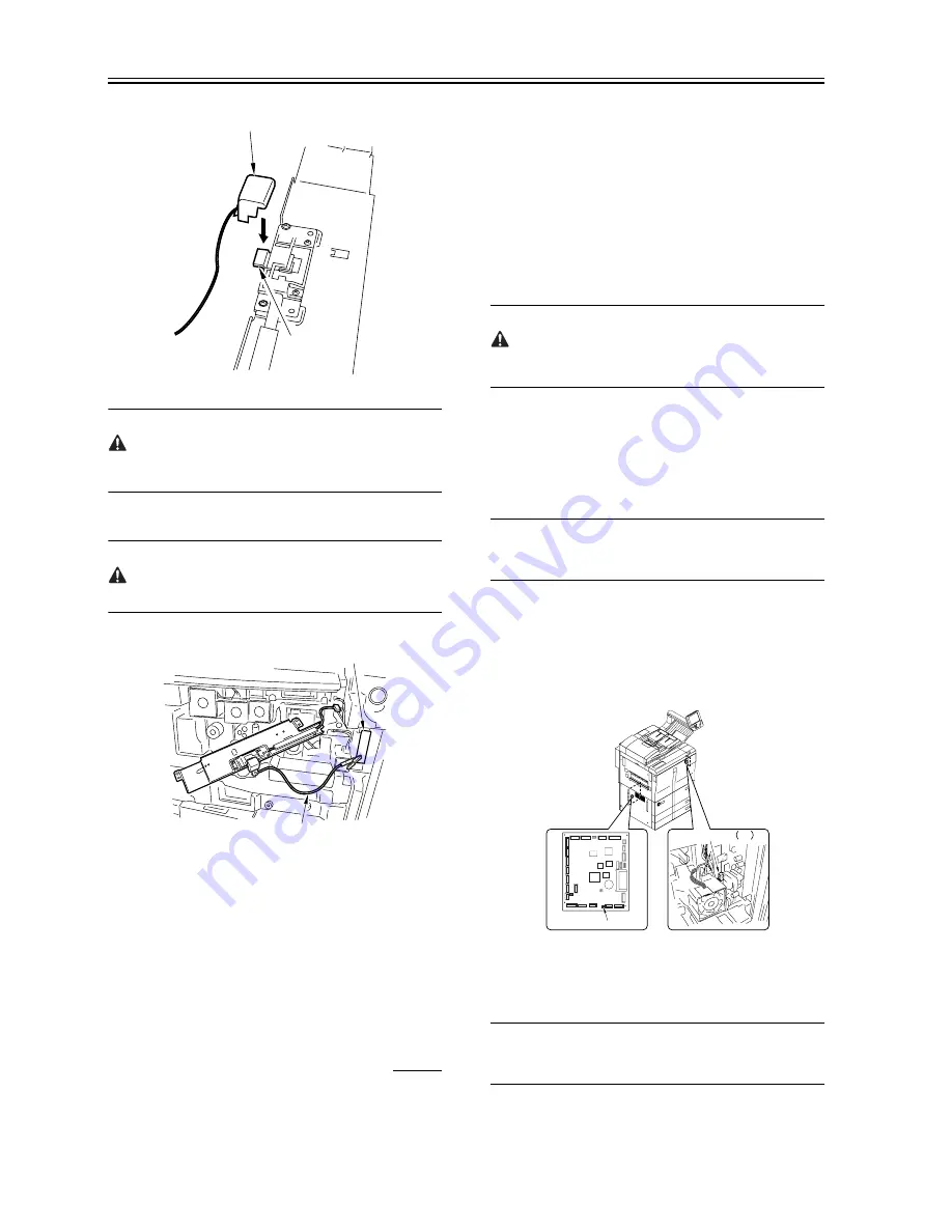
When mounting the potential sensor checking electrode to the potential
sensor, take care so that the magnet of the checking electrode will not
come into contact with the potential sensor cover.
10) Connect the cable [1] of the potential sensor checking electrode to
the frame (GND) [2] of the machine.
Be sure to allow enough space from the window of the sensor so the the
clip will not come into contact with the cover of the sensor.
F-14-94
11) Insert the door switch actuator into the door switch assembly.
12) Connect the power plug to the power outlet, and turn on the main
power switch.
13) Execute the following in service mode:
COPIER>FUNCTION>DPC>OFST.
14) Record the setting of 'OFST' on the service label.
15) Turn off the main power switch.
16) Disconnect the power plug from the power outlet.
17) Detach the potential sensor checking electrode.
18) Put the potential sensor support plate back into its initial position.
19) Connect the power plug to the power outlet, and turn on the main
power switch.
14.7.16 Checking the Surface Potential Control
System
0007-0720
iR105i/iR105+ / iR9070
a. Outline
If image faults occur, it is important to find out whether the cause is in
the latent static image formation block (including the photosensitive
drum and the potential control system) or it is in the developing/transfer
system, requiring a check on the surface potential. (You can check the
surface potential in service mode.)
b. Disabling the Auto Control Mechanisms
As a way of checking the mechanisms used for corona current control,
lamp intensity control, or developing bias control, you may disable the
auto control mechanisms (hereafter, non-auto control mode).
As a first-aid measure when a fault exists in the auto control mechanism,
you may use non-auto control mode; keep in mind that all outputs in
non-auto control mode are fixed to standard values.
1. Procedure
1) Make the following selections in service mode, and enter '0':
COPIER> OPTION> BODY> PO-CNT.
2) Press the Reset key twice.
In non-auto control mode, all settings used for coronal current control,
intensity control, developing bias control will be set to standard settings
stored in ROM.
2. Making Use of Non-Auto Control Mode
If a fault occurs in images, use the mode to find out if the cause is on the
input side or output side of the microprocessor on the DC controller
PCB.
In non-auto control mode, if the fault is corrected somewhat, you may
suspect the potential measurement unit or the DC controller PCB.
c. Zero-Level Check
One way of finding out if the surface potential control circuit is good or
not is to use a zero-level check.
MEMO:
A zero-level check is made to see if the microprocessor registers 0 V
when the surface potential of the drum is 0 V.
Using the result of the check, you can find out if the microprocessor on
the DC controller PCB or the measurement unit is good or not; a zero-
level check may take either of the following two methods:
1. Method 1
1) Turn off the power switch.
2) Short the connectors J522-1 and -2 on the DC controller PCB with a
jumper wire, and disconnect the connector J3 of the potential control
PCB.
F-14-95
3) Fit the door switch actuator into the door switch assembly, and turn
on the power switch.
4) Make the following selections in service mode, and check to see if the
reading is between 0 and 30 during initial rotation: COPIER>
DISPLAY> DPOT> DPOT-K.
MEMO:
If the reading is not as indicated, you may suspect a fault in the DC
controller PCB.
[1]
[2]
[1]
[2]
Connector
J3
J522
Summary of Contents for ImageRunner iR8500 Series
Page 1: ...Apr 5 2005 Service Manual iR8500 Series ...
Page 2: ......
Page 6: ......
Page 32: ...Contents ...
Page 33: ...Chapter 1 Introduction ...
Page 34: ......
Page 98: ......
Page 99: ...Chapter 2 Installation ...
Page 100: ......
Page 180: ...Chapter 2 2 78 F 2 272 2 1 1 3 ...
Page 181: ...Chapter 3 Basic Operation ...
Page 182: ......
Page 184: ......
Page 207: ...Chapter 4 Main Controller ...
Page 208: ......
Page 245: ...Chapter 4 4 35 F 4 72 1 2 ...
Page 246: ......
Page 247: ...Chapter 5 Original Exposure System ...
Page 248: ......
Page 252: ......
Page 306: ......
Page 307: ...Chapter 6 Image Processing System ...
Page 308: ......
Page 310: ......
Page 319: ...Chapter 7 Laser Exposure ...
Page 320: ......
Page 322: ......
Page 335: ...Chapter 8 Image Formation ...
Page 336: ......
Page 340: ......
Page 399: ...Chapter 9 Pickup Feeding System ...
Page 400: ......
Page 404: ......
Page 482: ......
Page 483: ...Chapter 10 Fixing System ...
Page 484: ......
Page 524: ......
Page 525: ...Chapter 11 External and Controls ...
Page 526: ......
Page 530: ......
Page 583: ...Chapter 12 MEAP ...
Page 584: ......
Page 586: ......
Page 589: ...Chapter 13 Maintenance and Inspection ...
Page 590: ......
Page 592: ......
Page 610: ...Chapter 13 13 18 F 13 17 1 2 3 ...
Page 648: ......
Page 649: ...Chapter 14 Standards and Adjustments ...
Page 650: ......
Page 654: ......
Page 723: ...Chapter 15 Correcting Faulty Images ...
Page 724: ......
Page 728: ......
Page 792: ......
Page 793: ...Chapter 16 Self Diagnosis ...
Page 794: ......
Page 796: ......
Page 841: ...Chapter 17 Service Mode ...
Page 842: ......
Page 1076: ......
Page 1077: ...Chapter 18 Upgrading ...
Page 1078: ......
Page 1080: ......
Page 1108: ...Chapter 18 18 28 F 18 45 3 Click Start F 18 46 4 Click Save F 18 47 5 Click OK ...
Page 1111: ...Chapter 19 Service Tools ...
Page 1112: ......
Page 1114: ......
Page 1120: ......
Page 1121: ...Apr 5 2005 ...
Page 1122: ......