


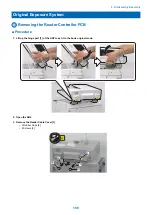
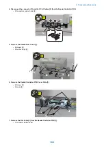


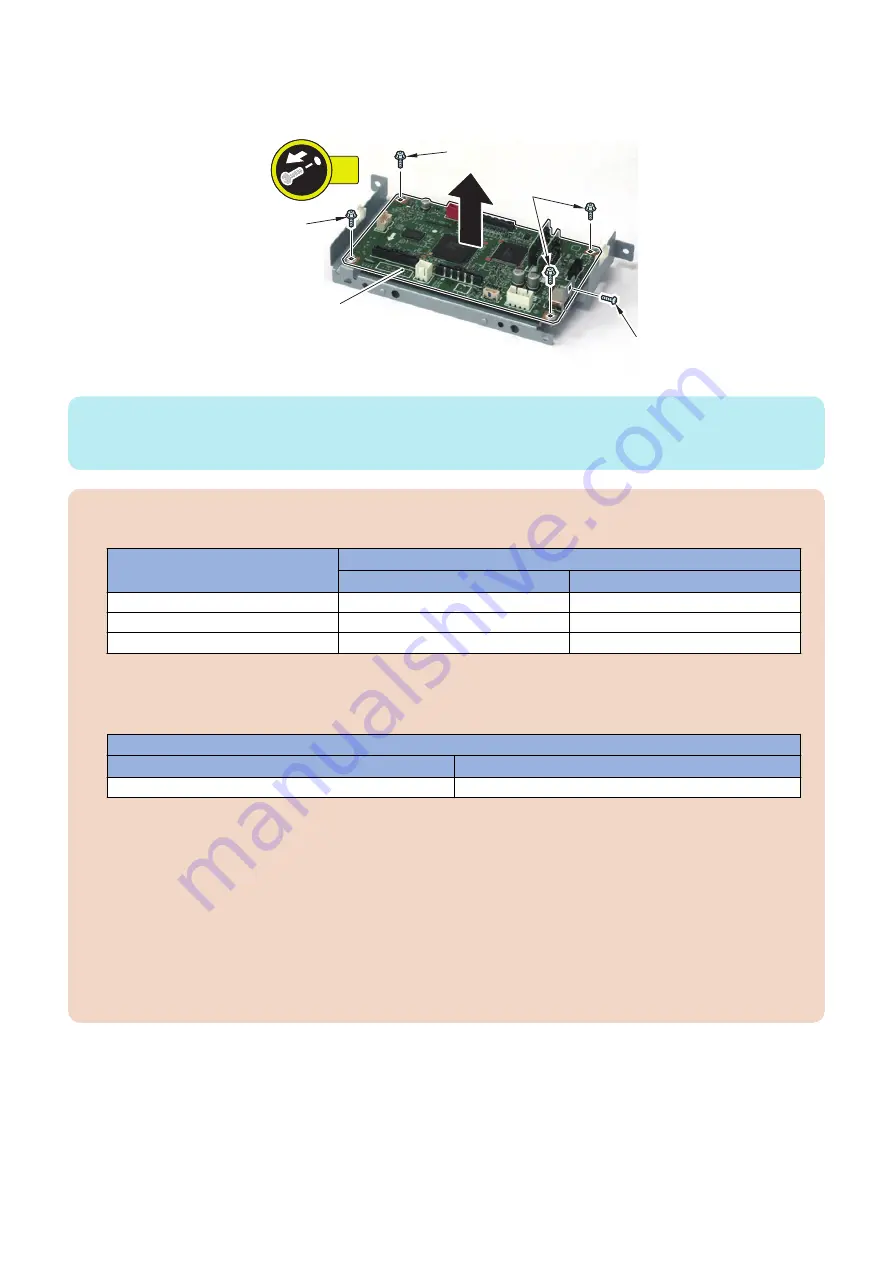
9. Remove the Reader Controller PCB [1].
• 1 Screw [2]
• 4 Screws [3]
[1]
[3]
[2]
[3]
[3]
5x
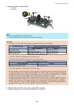
NOTE:
Caution when installing the Reader Controller PCB [1]
• When installing the Reader Controller PCB [1], tighten the screw [2] first.
CAUTION:
• The Reader Controller PCB in factory default setting is different by the host machine type.
Host Machine Type
Reader Controller PCB in factory default setting
PCB Configuration
Firmware
Reversal ADF model
Reversal ADF *
Reversal ADF model
Single pass ADF model
Single pass ADF model *
Single pass ADF model
ADF selectable model
Single pass / Reversal ADF model *
Reversal ADF model
*Connector configuration is different by the host machine type.
• The Reader Controller PCB for service part is 1 type described below.
Reader Controller PCB for service part
PCB Configuration
Firmware
Single pass / Reversal ADF model *
Reversal ADF model
*Connector configuration is different by the host machine type.
• When the Reader Controller PCB for service part is installed on the Single Pass ADF, a message prompting the user
to upgrading the firmware immediately after turning ON the host machine. When executing the upgrade following the
message, the firmware for the single pass ADF is installed. However, the firmware is not upgraded when the Reader
Controller PCB for service part is installed on the reversal ADF model or platen cover model.
• If upgrading the firmware is skipped, the ADF enters the limited functions mode. a "The feeder needs to be checked."
message is displayed in the status line and a "Ready to copy. (Functions Limited) Cannot use Feeder" message is
displayed on the copy screen. a message prompting the user to upgrading the firmware each time of turning ON or
OFF the host machine. In order to maintain consistency in versions for options, upgrade or downgrade the firmware
regardless of the setting in service mode > OPTION > FNC-SW > VER-CHNG.
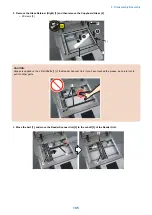
10. <When the ADF driver PCB and the reader controller PCB is replaced>
Actions after Replacement:
“Actions after Parts Replacement” on page 329
4. Disassembly/Assembly
191
Summary of Contents for imagerunner advance 4551i
Page 19: ...Product Overview 1 Product Lineup 7 Features 13 Specifications 16 Name of Parts 26 ...
Page 155: ...Periodical Service 3 Consumable Parts List 143 Cleaning Check Adjustment Locations 146 ...
Page 392: ...Error Jam Alarm 7 Overview 380 Error Code 383 Jam Code 509 Alarm Code 520 ...
Page 545: ...Service Mode 8 Overview 533 COPIER 549 FEEDER 845 SORTER 851 BOARD 871 ...
Page 892: ...Unpacking 1 2 1200 mm 840 mm 769 mm 1230 mm 2430 mm 3 9 Installation 879 ...
Page 895: ...3 4 NOTE Keep the removed screws for relocating the host machine 2x 5 6 7 9 Installation 882 ...
Page 896: ...8 9 10 1x Installing the Air Filter 1 9 Installation 883 ...
Page 897: ...2 3 Installing the Drum Unit 1 2 3 9 Installation 884 ...
Page 899: ...8 NOTE The screw removed at procedure 4 is used 1x 9 10 11 12 9 Installation 886 ...
Page 923: ...5 6 NOTE Use the screws and Rubber Caps removed in step 1 2x 7 2x 9 Installation 910 ...
Page 935: ...7 1x 8 9 6x 10 2x 9 Installation 922 ...
Page 936: ...11 Installing the NFC Kit 1 2 2x 3 TP M3x4 1x 9 Installation 923 ...
Page 938: ...4 5 1x 6 9 Installation 925 ...
Page 985: ...8 2x 2x TP M4x8 Black When installing the USB Keyboard 1 9 Installation 972 ...
Page 991: ...7 4x 8 1x 1x Lower Cover 9 1x 10 1x 1x 9 Installation 978 ...
Page 992: ...11 1x 1x 12 1x 13 TP M3x12 2x 14 4x TP M3x6 9 Installation 979 ...
Page 997: ...Installation Procedure 1 2 2x 3 2x 4 6x 5 4x 9 Installation 984 ...
Page 998: ...6 7 NOTE Do not close the Wire Saddle 1x 1x 8 9 9 Installation 985 ...
Page 1003: ...2 1x 1x 3 2x 2x 4 9 Installation 990 ...
Page 1012: ...2 1x 1x 3 2x 2x 4 9 Installation 999 ...
Page 1014: ...7 CAUTION The connector must be contacted TP㸹M3x6 3x 1x 8 4x 9 9 Installation 1001 ...
Page 1016: ...13 4x 14 15 Binding M4x16 Binding M3x16 2x M3x16 M4x16 16 Binding M4x6 1x 9 Installation 1003 ...
Page 1023: ...Installation Procedure Preparation 1 4x 2 1x 1x 3 2x 9 Installation 1010 ...
Page 1029: ...4 5 1x 1x 9 Installation 1016 ...
Page 1048: ...3 2x TP M3x8 Black 4 2x TP M3x6 5 9 Installation 1035 ...
Page 1053: ... Installing the Removable HDD Kit 1 2x 2x 2 3 1x 4 9 Installation 1040 ...
Page 1065: ...3 2x TP M3x8 Black 4 2x TP M3x6 5 9 Installation 1052 ...
Page 1071: ... Installing the Removable HDD Kit 1 2x 2x 2 3 1x 4 9 Installation 1058 ...


