

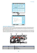

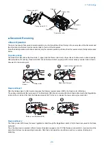

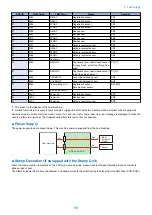
Location
Jam code
Sensor name
Sensor number
Jam type
Delay
Stationary
Residual
01
0046
ADF Registration Sensor PS_R2
-
Yes
-
0007
ADF Lead Sensor 1
PS_A6
Yes
-
-
0047
Yes
-
-
0008
-
Yes
-
0048
-
Yes
-
0009
ADF Lead Sensor 2
PS_A7
Yes
-
-
0049
Yes
-
-
0010
-
Yes
-
0050
-
Yes
-
0094
Entire Feed System Sen-
sor
-
-
-
Yes
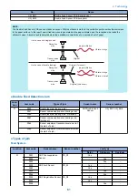
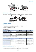
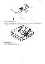
Others
Location
Jam code
Jam type
Sensor name
Sensor number
01
0090
DADF open
DADF Open/Close Sen-
sor 1/2
Reader: PS_N1, PS_N2
0091
DADF opened by user
0092
Cover open
Cover Open/Closed Sen-
sor
PS_A5
0093
Cover opened by user
0095
Pickup error
Post-separation Sensor
PS_R1
0071
Software timing error*1
-
-
0073
Error avoidance jam*2
-
-
0096
Limited functions jam*3
-
-
*1 It occurs when a software sequence error has occurred for some reasons. The machine is recovered by opening and then
closing the cover to remove jammed paper.
*2 An error which is handled as an error code occurs. It is highly possible that the machine is recovered by opening and then
closing the cover. Therefore, the jam message is indicated to make the user to open and then close the cover to recover the
machine. If the machine is not recovered by opening and then closing the cover, refer to the error log, and perform the remedy
for the error code which has occurred at the same time.
*3 Limited functions jam is a jam for preventing an original to be left inside the machine when a problem which requires the
machine moves to limited functions mode occurs. If an error occurs for some reasons, a jam message is displayed to make the
user to perform jam removal. After that, an error is displayed, and the device enters limited functions mode. The machine recovers
when the cause of the error is solved.
If this jam occurs, refer to the error log, and perform the remedy for the error code which has occurred at the same time.
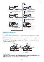
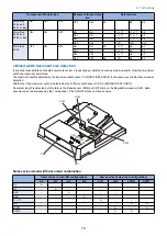
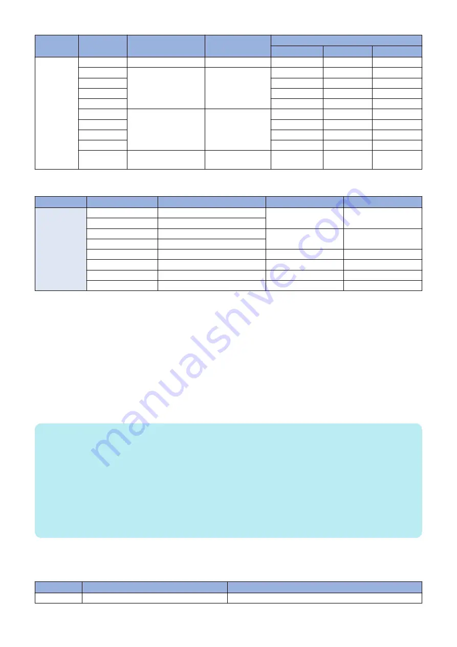
NOTE:
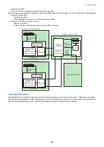
Settings/Registration (method for resuming when a feeder paper jam occurs)
When performing stream reading, the method for resuming after a jam has occurred can be set.
Setting item is as follow.
• From 1st Page: After removing the jam, load all original pages in the Document Pickup Tray again. After the Start key is
pressed, the machine feeds the original pages that were already read until the jam occurred without reading them again, and
resume reading of the remaining pages. (Default)
• From Stopped Original: After removing the jam, only load the original pages that have not yet been read in the Document
Pickup Tray again. After the Start key is pressed, the machine resumes reading of the remaining pages.
This equipment supports stream reading of 150 original pages (80 g/m
2
), so if a jam occurs at the 149th page of a 150 page
original, for example, it can take up to 2 minutes to resume reading if all the original pages are loaded again. Resuming from the
original page where reading stopped enables shorter jam recovery times.
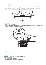
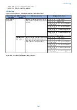
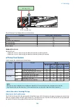
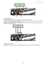
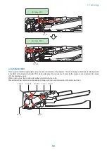
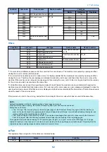
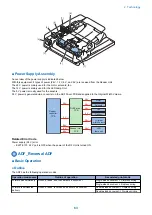
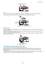
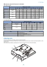
■ Fan
This equipment has a single fan. Its functions are indicated below.
Code
Name
Function
FAN_A1
ADF Cooling Fan
Cooling the ADF Driver PCB (UN_BO1) and 3 motors
2. Technology
62
Summary of Contents for imagerunner advance 4551i
Page 19: ...Product Overview 1 Product Lineup 7 Features 13 Specifications 16 Name of Parts 26 ...
Page 155: ...Periodical Service 3 Consumable Parts List 143 Cleaning Check Adjustment Locations 146 ...
Page 392: ...Error Jam Alarm 7 Overview 380 Error Code 383 Jam Code 509 Alarm Code 520 ...
Page 545: ...Service Mode 8 Overview 533 COPIER 549 FEEDER 845 SORTER 851 BOARD 871 ...
Page 892: ...Unpacking 1 2 1200 mm 840 mm 769 mm 1230 mm 2430 mm 3 9 Installation 879 ...
Page 895: ...3 4 NOTE Keep the removed screws for relocating the host machine 2x 5 6 7 9 Installation 882 ...
Page 896: ...8 9 10 1x Installing the Air Filter 1 9 Installation 883 ...
Page 897: ...2 3 Installing the Drum Unit 1 2 3 9 Installation 884 ...
Page 899: ...8 NOTE The screw removed at procedure 4 is used 1x 9 10 11 12 9 Installation 886 ...
Page 923: ...5 6 NOTE Use the screws and Rubber Caps removed in step 1 2x 7 2x 9 Installation 910 ...
Page 935: ...7 1x 8 9 6x 10 2x 9 Installation 922 ...
Page 936: ...11 Installing the NFC Kit 1 2 2x 3 TP M3x4 1x 9 Installation 923 ...
Page 938: ...4 5 1x 6 9 Installation 925 ...
Page 985: ...8 2x 2x TP M4x8 Black When installing the USB Keyboard 1 9 Installation 972 ...
Page 991: ...7 4x 8 1x 1x Lower Cover 9 1x 10 1x 1x 9 Installation 978 ...
Page 992: ...11 1x 1x 12 1x 13 TP M3x12 2x 14 4x TP M3x6 9 Installation 979 ...
Page 997: ...Installation Procedure 1 2 2x 3 2x 4 6x 5 4x 9 Installation 984 ...
Page 998: ...6 7 NOTE Do not close the Wire Saddle 1x 1x 8 9 9 Installation 985 ...
Page 1003: ...2 1x 1x 3 2x 2x 4 9 Installation 990 ...
Page 1012: ...2 1x 1x 3 2x 2x 4 9 Installation 999 ...
Page 1014: ...7 CAUTION The connector must be contacted TP㸹M3x6 3x 1x 8 4x 9 9 Installation 1001 ...
Page 1016: ...13 4x 14 15 Binding M4x16 Binding M3x16 2x M3x16 M4x16 16 Binding M4x6 1x 9 Installation 1003 ...
Page 1023: ...Installation Procedure Preparation 1 4x 2 1x 1x 3 2x 9 Installation 1010 ...
Page 1029: ...4 5 1x 1x 9 Installation 1016 ...
Page 1048: ...3 2x TP M3x8 Black 4 2x TP M3x6 5 9 Installation 1035 ...
Page 1053: ... Installing the Removable HDD Kit 1 2x 2x 2 3 1x 4 9 Installation 1040 ...
Page 1065: ...3 2x TP M3x8 Black 4 2x TP M3x6 5 9 Installation 1052 ...
Page 1071: ... Installing the Removable HDD Kit 1 2x 2x 2 3 1x 4 9 Installation 1058 ...


