


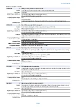
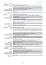

COPIER > FUNCTION > CLEAR
CA-KEY
2
Deletion of CA certificate and key pair
Detail
*Operation on this item is restricted by the setting of [Restrict Service Representation Access].
To simultaneously delete the CA certificate and key pair which are additionally registered by the
user.
Use Case
When a service person replaces/discards the device
Adj/Set/Operate Method
1) Select the item, and then press OK key.
2) Check that OK is displayed.
3) Turn OFF/ON the main power switch.
Caution
- Unless this item is executed at the time of replacement/discard of the device, the CA certificate
and key pair which are additionally registered by the user remain in the HDD, which is a problem
in terms of security.
- Do not execute this item carelessly because the CA certificate and key pair which are additionally
registered are deleted when it is executed. If they are deleted mistakenly, they need to be again
registered by the user. If no CA certificate and key pair are additionally registered, the machine
condition becomes the same as the one at the time of factory shipment.
- When NG is displayed in 2), there is a possibility that deletion was not executed. In this case,
surely execute the deletion by initializing the HDD, etc.
Display/Adj/Set Range
At normal termination: OK, At abnormal termination: NG
Supplement/Memo
- The CA certificate is used in the MEAP application with E-RDS and SSL client connection, and
the key pair is used in the SSL function of IPP, RUI and MEAP.
- When the main power switch is turned OFF/ON, the CA certificate and key pair which were
registered at the time of factory shipment are decompressed from the archive (/BOOTDEV/
KCMNG), and become available in the E-RDS/SSL function.
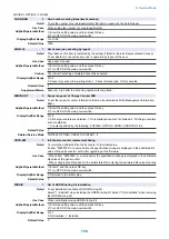
ERDS-DAT
1
Initialization of E-RDS SRAM data
Detail
To initialize the SCM value of the Embedded-RDS stored in the SRAM.
SCM values are ON/OFF of E-RDS, server's port number, server's SOAP URL, and
communication schedule with the server (how often the data is acquired), etc.
The value set by E-RDS, RGW-PORT, RGW-ADR, COM-LOG is cleared.
Use Case
When upgrading the Bootable in the E-RDS environment
Adj/Set/Operate Method
Select the item, and then press OK key.
Caution
The method of using the SRAM in E-RDS differs depending on the Bootable version. Therefore,
unless the SRAM data is cleared at the time of version upgrade, data inconsistency occurs.
Display/Adj/Set Range
At normal termination: OK, At abnormal termination: NG
Related Service Mode
COPIER> FUNCTION> INSTALL> E-RDS, RGW-PORT, RGW-ADR, COM-LOG
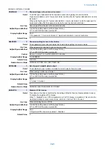
USBM-CLR
1
Initialize USB MEAP priority rgst info
Detail
To initialize the registered ID data retained in the OS field by calling the API provided by the OS.
Use Case
When a failure occurs in USB MEAP priority registration
Adj/Set/Operate Method
Select the item, and then press OK key.
JV-CACHE
1
Cache clear of JAVA application
Detail
*Operation on this item is restricted by the setting of [Restrict Service Representation Access].
To clear the cache information used by JAVA application.
Use Case
When initializing the JAVA application
Adj/Set/Operate Method
Select the item, and then press OK key.
8. Service Mode
708
Summary of Contents for imagerunner advance 4551i
Page 19: ...Product Overview 1 Product Lineup 7 Features 13 Specifications 16 Name of Parts 26 ...
Page 155: ...Periodical Service 3 Consumable Parts List 143 Cleaning Check Adjustment Locations 146 ...
Page 392: ...Error Jam Alarm 7 Overview 380 Error Code 383 Jam Code 509 Alarm Code 520 ...
Page 545: ...Service Mode 8 Overview 533 COPIER 549 FEEDER 845 SORTER 851 BOARD 871 ...
Page 892: ...Unpacking 1 2 1200 mm 840 mm 769 mm 1230 mm 2430 mm 3 9 Installation 879 ...
Page 895: ...3 4 NOTE Keep the removed screws for relocating the host machine 2x 5 6 7 9 Installation 882 ...
Page 896: ...8 9 10 1x Installing the Air Filter 1 9 Installation 883 ...
Page 897: ...2 3 Installing the Drum Unit 1 2 3 9 Installation 884 ...
Page 899: ...8 NOTE The screw removed at procedure 4 is used 1x 9 10 11 12 9 Installation 886 ...
Page 923: ...5 6 NOTE Use the screws and Rubber Caps removed in step 1 2x 7 2x 9 Installation 910 ...
Page 935: ...7 1x 8 9 6x 10 2x 9 Installation 922 ...
Page 936: ...11 Installing the NFC Kit 1 2 2x 3 TP M3x4 1x 9 Installation 923 ...
Page 938: ...4 5 1x 6 9 Installation 925 ...
Page 985: ...8 2x 2x TP M4x8 Black When installing the USB Keyboard 1 9 Installation 972 ...
Page 991: ...7 4x 8 1x 1x Lower Cover 9 1x 10 1x 1x 9 Installation 978 ...
Page 992: ...11 1x 1x 12 1x 13 TP M3x12 2x 14 4x TP M3x6 9 Installation 979 ...
Page 997: ...Installation Procedure 1 2 2x 3 2x 4 6x 5 4x 9 Installation 984 ...
Page 998: ...6 7 NOTE Do not close the Wire Saddle 1x 1x 8 9 9 Installation 985 ...
Page 1003: ...2 1x 1x 3 2x 2x 4 9 Installation 990 ...
Page 1012: ...2 1x 1x 3 2x 2x 4 9 Installation 999 ...
Page 1014: ...7 CAUTION The connector must be contacted TP㸹M3x6 3x 1x 8 4x 9 9 Installation 1001 ...
Page 1016: ...13 4x 14 15 Binding M4x16 Binding M3x16 2x M3x16 M4x16 16 Binding M4x6 1x 9 Installation 1003 ...
Page 1023: ...Installation Procedure Preparation 1 4x 2 1x 1x 3 2x 9 Installation 1010 ...
Page 1029: ...4 5 1x 1x 9 Installation 1016 ...
Page 1048: ...3 2x TP M3x8 Black 4 2x TP M3x6 5 9 Installation 1035 ...
Page 1053: ... Installing the Removable HDD Kit 1 2x 2x 2 3 1x 4 9 Installation 1040 ...
Page 1065: ...3 2x TP M3x8 Black 4 2x TP M3x6 5 9 Installation 1052 ...
Page 1071: ... Installing the Removable HDD Kit 1 2x 2x 2 3 1x 4 9 Installation 1058 ...


