


■ NETWORK
COPIER > TEST > NETWORK
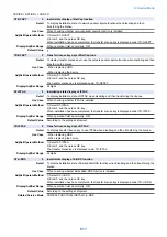
PING
1
Network connection check
Detail
To check connection between this machine and TCP/IP network.
Use Case
- When checking network connection at the time of installation
- At network connection failure
Adj/Set/Operate Method
1) Turn OFF the main power switch.
2) Connect the network cable to this machine, and then turn ON the main power switch.
3) Inform the system administrator at user's site that installation of this machine is complete, and
ask for network setting.
4) Ask the system administrator to check the network connection, and check the remote host
address of PING transmission target.
5) Select the item and enter the remote host address, and then press OK key and Start key.
OK: Connection is normal. Checking procedure is complete.
NG: Connection failed. Go to step 6) if the cable connection is OK. In case of cable connection
failure, connect again and then go to step 5).
6) Select the item and enter loopback address, and then press OK key and Start key.
OK: TCP/IP setting of this machine is normal. Go to step 7) to check NIC.
NG: TCP/IP setting of this machine has failure. Go to step 3) to check the setting again.
7) Select the item and enter the local host address, and then press OK key.
OK: Network setting of this machine and NIC are normal. Inform the system administrator that the
trouble is due to network environment and ask for countermeasure.
NG: Connection failure/fault with NIC. Check connection of NIC/ replace NIC.
Display/Adj/Set Range
0.0.0.0 to 255.255.255.255
At normal state: OK
At failure occurrence: NG
Supplement/Memo
- Remote host address: IP address of PC terminal in network.
- Loopback address: 127.0.0.1. Checking TCP/IP of this machine is available because the signal
is returned before NIC.
- NIC: Network interface board
- Local host address: IP address of this machine
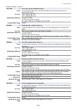
BML-DISP
2
Set System Monitor scrn: BMlinks support
Detail
To set whether to display only the device configuration in the System Monitor screen when
supporting BMlinks.
When the setting is switched, the job status and logs are not displayed.
Use Case
When supporting BMlinks
Adj/Set/Operate Method
Enter the setting value, and then press OK key.
Display/Adj/Set Range
0 to 1
0: Ordinary System Monitor screen, 1: Screen in which only the device configuration is displayed
Default Value
0
IPV6-ADR
1
Setting of PING send address (IPv6)
Detail
To set the IPv6 address to send PING.
When PING is sent to this address by COPIER> TEST> NETWORK> PING-IP6, the network
connection condition in the IPv6 environment can be checked.
Adj/Set/Operate Method
Enter the setting value, and then press OK key.
Caution
- Enter a consistent character string as an address of IPv6.
- Enter an address within 39 characters including hexadecimal numbers (0-9, a-f) and a separator
(:).
Related Service Mode
COPIER> TEST> NETWORK> PING-IP6
PING-IP6
1
PING transmission to IPv6 address
Detail
To send PING to the address specified by IPV6-ADR.
The network connection condition in the IPv6 environment can be checked.
Adj/Set/Operate Method
Select the item, and then press OK key.
Related Service Mode
COPIER> TEST> NETWORK> IPV6-ADR
8. Service Mode
819
Summary of Contents for imagerunner advance 4551i
Page 19: ...Product Overview 1 Product Lineup 7 Features 13 Specifications 16 Name of Parts 26 ...
Page 155: ...Periodical Service 3 Consumable Parts List 143 Cleaning Check Adjustment Locations 146 ...
Page 392: ...Error Jam Alarm 7 Overview 380 Error Code 383 Jam Code 509 Alarm Code 520 ...
Page 545: ...Service Mode 8 Overview 533 COPIER 549 FEEDER 845 SORTER 851 BOARD 871 ...
Page 892: ...Unpacking 1 2 1200 mm 840 mm 769 mm 1230 mm 2430 mm 3 9 Installation 879 ...
Page 895: ...3 4 NOTE Keep the removed screws for relocating the host machine 2x 5 6 7 9 Installation 882 ...
Page 896: ...8 9 10 1x Installing the Air Filter 1 9 Installation 883 ...
Page 897: ...2 3 Installing the Drum Unit 1 2 3 9 Installation 884 ...
Page 899: ...8 NOTE The screw removed at procedure 4 is used 1x 9 10 11 12 9 Installation 886 ...
Page 923: ...5 6 NOTE Use the screws and Rubber Caps removed in step 1 2x 7 2x 9 Installation 910 ...
Page 935: ...7 1x 8 9 6x 10 2x 9 Installation 922 ...
Page 936: ...11 Installing the NFC Kit 1 2 2x 3 TP M3x4 1x 9 Installation 923 ...
Page 938: ...4 5 1x 6 9 Installation 925 ...
Page 985: ...8 2x 2x TP M4x8 Black When installing the USB Keyboard 1 9 Installation 972 ...
Page 991: ...7 4x 8 1x 1x Lower Cover 9 1x 10 1x 1x 9 Installation 978 ...
Page 992: ...11 1x 1x 12 1x 13 TP M3x12 2x 14 4x TP M3x6 9 Installation 979 ...
Page 997: ...Installation Procedure 1 2 2x 3 2x 4 6x 5 4x 9 Installation 984 ...
Page 998: ...6 7 NOTE Do not close the Wire Saddle 1x 1x 8 9 9 Installation 985 ...
Page 1003: ...2 1x 1x 3 2x 2x 4 9 Installation 990 ...
Page 1012: ...2 1x 1x 3 2x 2x 4 9 Installation 999 ...
Page 1014: ...7 CAUTION The connector must be contacted TP㸹M3x6 3x 1x 8 4x 9 9 Installation 1001 ...
Page 1016: ...13 4x 14 15 Binding M4x16 Binding M3x16 2x M3x16 M4x16 16 Binding M4x6 1x 9 Installation 1003 ...
Page 1023: ...Installation Procedure Preparation 1 4x 2 1x 1x 3 2x 9 Installation 1010 ...
Page 1029: ...4 5 1x 1x 9 Installation 1016 ...
Page 1048: ...3 2x TP M3x8 Black 4 2x TP M3x6 5 9 Installation 1035 ...
Page 1053: ... Installing the Removable HDD Kit 1 2x 2x 2 3 1x 4 9 Installation 1040 ...
Page 1065: ...3 2x TP M3x8 Black 4 2x TP M3x6 5 9 Installation 1052 ...
Page 1071: ... Installing the Removable HDD Kit 1 2x 2x 2 3 1x 4 9 Installation 1058 ...


