


Checking the Contents....................................................................................................................880
Installation Procedure......................................................................................................................881
Removing the Packaging Materials ....................................................................................................881
Installing the Air Filter........................................................................................................................ 883
Installing the Drum Unit......................................................................................................................884
Installing the Toner Cartridge............................................................................................................. 887
Connecting with the Cables................................................................................................................888
Setting the Environment Heater Switch............................................................................................... 888
Installing IC Card Reader (EUR Only).................................................................................................889
Turning ON the Main Power...............................................................................................................893
Setting the Host Machine................................................................................................................... 894
Installing the Tray..............................................................................................................................895
Setting the Cassette.......................................................................................................................... 895
Other Installations............................................................................................................................. 897
Adjusting Image Position....................................................................................................................900
Checking Network Connection........................................................................................................... 901
Troubleshooting of Network............................................................................................................... 902
When Relocating the Host Machine................................................................................................904
Platen Cover Type W...................................................................................................................... 906
Checking the Contents...................................................................................................................... 914
Check Item When Turning OFF the Main Power..................................................................................914
Installation Outline Drawing................................................................................................................914
Installation Procedure........................................................................................................................ 914
Operation Check............................................................................................................................... 919
Points to Note at Installation...............................................................................................................920
Checking the Contents...................................................................................................................... 920
Check Item When Turning OFF the Main Power..................................................................................920
Installation Outline Drawing................................................................................................................920
Remove the Control Panel................................................................................................................. 920
Installing the NFC Kit.........................................................................................................................923
Installing the Control Panel................................................................................................................ 924
Affixing the NFC Target..................................................................................................................... 927
Setting after Installation..................................................................................................................... 927
Checking the Contents...................................................................................................................... 928
Check Item When Turning OFF the Main Power..................................................................................928
Installation Outline Drawing................................................................................................................928
Installation Procedure........................................................................................................................ 928
Setting after Installation..................................................................................................................... 931
Checking Before Installation...............................................................................................................932
Checking the Contents...................................................................................................................... 932
Installation Procedure (When the Cassette Heater PCB as standard is installed)................................... 932
Installation Procedure (When the Cassette Heater PCB as standard is not installed)............................. 935
Contents
vii
Summary of Contents for imagerunner advance 4551i
Page 19: ...Product Overview 1 Product Lineup 7 Features 13 Specifications 16 Name of Parts 26 ...
Page 155: ...Periodical Service 3 Consumable Parts List 143 Cleaning Check Adjustment Locations 146 ...
Page 392: ...Error Jam Alarm 7 Overview 380 Error Code 383 Jam Code 509 Alarm Code 520 ...
Page 545: ...Service Mode 8 Overview 533 COPIER 549 FEEDER 845 SORTER 851 BOARD 871 ...
Page 892: ...Unpacking 1 2 1200 mm 840 mm 769 mm 1230 mm 2430 mm 3 9 Installation 879 ...
Page 895: ...3 4 NOTE Keep the removed screws for relocating the host machine 2x 5 6 7 9 Installation 882 ...
Page 896: ...8 9 10 1x Installing the Air Filter 1 9 Installation 883 ...
Page 897: ...2 3 Installing the Drum Unit 1 2 3 9 Installation 884 ...
Page 899: ...8 NOTE The screw removed at procedure 4 is used 1x 9 10 11 12 9 Installation 886 ...
Page 923: ...5 6 NOTE Use the screws and Rubber Caps removed in step 1 2x 7 2x 9 Installation 910 ...
Page 935: ...7 1x 8 9 6x 10 2x 9 Installation 922 ...
Page 936: ...11 Installing the NFC Kit 1 2 2x 3 TP M3x4 1x 9 Installation 923 ...
Page 938: ...4 5 1x 6 9 Installation 925 ...
Page 985: ...8 2x 2x TP M4x8 Black When installing the USB Keyboard 1 9 Installation 972 ...
Page 991: ...7 4x 8 1x 1x Lower Cover 9 1x 10 1x 1x 9 Installation 978 ...
Page 992: ...11 1x 1x 12 1x 13 TP M3x12 2x 14 4x TP M3x6 9 Installation 979 ...
Page 997: ...Installation Procedure 1 2 2x 3 2x 4 6x 5 4x 9 Installation 984 ...
Page 998: ...6 7 NOTE Do not close the Wire Saddle 1x 1x 8 9 9 Installation 985 ...
Page 1003: ...2 1x 1x 3 2x 2x 4 9 Installation 990 ...
Page 1012: ...2 1x 1x 3 2x 2x 4 9 Installation 999 ...
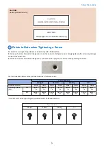
Page 1014: ...7 CAUTION The connector must be contacted TP㸹M3x6 3x 1x 8 4x 9 9 Installation 1001 ...
Page 1016: ...13 4x 14 15 Binding M4x16 Binding M3x16 2x M3x16 M4x16 16 Binding M4x6 1x 9 Installation 1003 ...
Page 1023: ...Installation Procedure Preparation 1 4x 2 1x 1x 3 2x 9 Installation 1010 ...
Page 1029: ...4 5 1x 1x 9 Installation 1016 ...
Page 1048: ...3 2x TP M3x8 Black 4 2x TP M3x6 5 9 Installation 1035 ...
Page 1053: ... Installing the Removable HDD Kit 1 2x 2x 2 3 1x 4 9 Installation 1040 ...
Page 1065: ...3 2x TP M3x8 Black 4 2x TP M3x6 5 9 Installation 1052 ...
Page 1071: ... Installing the Removable HDD Kit 1 2x 2x 2 3 1x 4 9 Installation 1058 ...


