


COPIER > FUNCTION > INSTALL
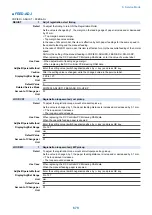
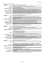
CNT-INTV
1
Set counter send interval to SC server
Detail
To set the interval of sending counter information to the sales company's server in a unit of one
hour.
This is displayed only when the Embedded-RDS third-party extended function is available.
Use Case
When using the Embedded-RDS third-party extended function
Adj/Set/Operate Method
1) Enter the setting value, and then press OK key.
2) Turn OFF/ON the main power switch.
Display/Adj/Set Range
1 to 168 (=1 week)
Unit
hour
Default Value
24
Supplement/Memo
Embedded-RDS: Function to send device information such as the device counter, failure, and
consumables to the sales company's server via SOAP protocol
Amount of Change per
Unit
1
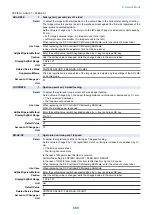
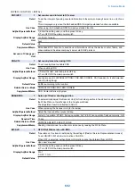
CDS-CTL
1
Set country/area when using CDS
Detail
To set country/area to enable CDS.
Use Case
When enabling CDS
Adj/Set/Operate Method
1) Select the item, and then press OK key.
2) Turn OFF/ON the main power switch.
Display/Adj/Set Range
Country/area set in COPIER> OPTION> FNC-SW> CONFIG, CA (Canada), LA (Latin America)
and HK (Hong Kong)
Default Value
It differs according to the location.
Related Service Mode
COPIER> OPTION> FNC-SW> CONFIG
Supplement/Memo
CDS: Contents Delivery System
RDSHDPOS
1
Auto adj of Reader shading position
Detail
To automatically adjust the Scanner Unit (for front side) position in feed direction when reading
the White Plate on the left edge of the Copyboard Glass.
The adjustment result is reflected to ADJ-S.
Use Case
When replacing the Scanner Unit (for front side)
Adj/Set/Operate Method
Select the item, and then press OK key.
Display/Adj/Set Range
At start of operation: START, During operation: ACTIVE, When operation finished normally: OK!
Required Time
10 sec
Related Service Mode
COPIER> ADJUST> ADJ-XY> ADJ-S
Supplement/Memo
Shading: It determines the white color reference by reading the White Plate.
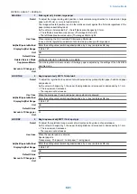
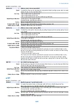
BIT-SVC
1
OFF/ON of Web service of E-RDS
Detail
*Operation on this item is restricted by the setting of [Restrict Service Representation Access].
To set ON/OFF of Web service function of E-RDS.
When OFF is selected, authentication information cannot be obtained from E-RDS.
Use Case
Upon user's request
Adj/Set/Operate Method
1) Enter the setting value, and then press OK key.
2) Turn OFF/ON the main power switch.
Display/Adj/Set Range
0 to 1
0: OFF, 1: ON
Default Value
1
8. Service Mode
692
Summary of Contents for imagerunner advance 4551i
Page 19: ...Product Overview 1 Product Lineup 7 Features 13 Specifications 16 Name of Parts 26 ...
Page 155: ...Periodical Service 3 Consumable Parts List 143 Cleaning Check Adjustment Locations 146 ...
Page 392: ...Error Jam Alarm 7 Overview 380 Error Code 383 Jam Code 509 Alarm Code 520 ...
Page 545: ...Service Mode 8 Overview 533 COPIER 549 FEEDER 845 SORTER 851 BOARD 871 ...
Page 892: ...Unpacking 1 2 1200 mm 840 mm 769 mm 1230 mm 2430 mm 3 9 Installation 879 ...
Page 895: ...3 4 NOTE Keep the removed screws for relocating the host machine 2x 5 6 7 9 Installation 882 ...
Page 896: ...8 9 10 1x Installing the Air Filter 1 9 Installation 883 ...
Page 897: ...2 3 Installing the Drum Unit 1 2 3 9 Installation 884 ...
Page 899: ...8 NOTE The screw removed at procedure 4 is used 1x 9 10 11 12 9 Installation 886 ...
Page 923: ...5 6 NOTE Use the screws and Rubber Caps removed in step 1 2x 7 2x 9 Installation 910 ...
Page 935: ...7 1x 8 9 6x 10 2x 9 Installation 922 ...
Page 936: ...11 Installing the NFC Kit 1 2 2x 3 TP M3x4 1x 9 Installation 923 ...
Page 938: ...4 5 1x 6 9 Installation 925 ...
Page 985: ...8 2x 2x TP M4x8 Black When installing the USB Keyboard 1 9 Installation 972 ...
Page 991: ...7 4x 8 1x 1x Lower Cover 9 1x 10 1x 1x 9 Installation 978 ...
Page 992: ...11 1x 1x 12 1x 13 TP M3x12 2x 14 4x TP M3x6 9 Installation 979 ...
Page 997: ...Installation Procedure 1 2 2x 3 2x 4 6x 5 4x 9 Installation 984 ...
Page 998: ...6 7 NOTE Do not close the Wire Saddle 1x 1x 8 9 9 Installation 985 ...
Page 1003: ...2 1x 1x 3 2x 2x 4 9 Installation 990 ...
Page 1012: ...2 1x 1x 3 2x 2x 4 9 Installation 999 ...
Page 1014: ...7 CAUTION The connector must be contacted TP㸹M3x6 3x 1x 8 4x 9 9 Installation 1001 ...
Page 1016: ...13 4x 14 15 Binding M4x16 Binding M3x16 2x M3x16 M4x16 16 Binding M4x6 1x 9 Installation 1003 ...
Page 1023: ...Installation Procedure Preparation 1 4x 2 1x 1x 3 2x 9 Installation 1010 ...
Page 1029: ...4 5 1x 1x 9 Installation 1016 ...
Page 1048: ...3 2x TP M3x8 Black 4 2x TP M3x6 5 9 Installation 1035 ...
Page 1053: ... Installing the Removable HDD Kit 1 2x 2x 2 3 1x 4 9 Installation 1040 ...
Page 1065: ...3 2x TP M3x8 Black 4 2x TP M3x6 5 9 Installation 1052 ...
Page 1071: ... Installing the Removable HDD Kit 1 2x 2x 2 3 1x 4 9 Installation 1058 ...


