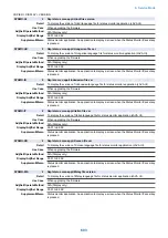

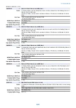
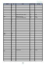


COPIER > DISPLAY > CCD
GAIN-ER
2
Gain lvl of Read Sensor even bit(R):frt
Detail
To display the Red gain level adjustment value in even-numbered bit on the Reading Sensor of
Scanner Unit (for front side).
Continuous display of upper limit is considered a failure of the Scanner Unit/Reader Controller
PCB.
When the value is out of the target value range, image failure or E302 (shading error) may have
occurred. Identify the cause according to the value.
Use Case
- When replacing the Reader Controller PCB
- At scanned image failure
Adj/Set/Operate Method
N/A (Display only)
Display/Adj/Set Range
0 to 65535
Appropriate Target Value
0 - 143
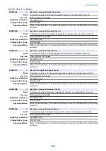
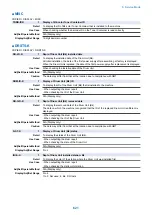
LAMP-BW
2
Dspl LED light intnsty adj VL:B&W, front
Detail
To display the LED light intensity adjustment value of Scanner Unit (for front side) in B&W scanning
mode.
Use Case
When image failure occurs at front side scanning in black mode
Adj/Set/Operate Method
N/A (Display only)
Display/Adj/Set Range
55 to 275
Appropriate Target Value
100 - 275
Supplement/Memo
LED cannot be replaced individually. Replace the Scanner Unit.
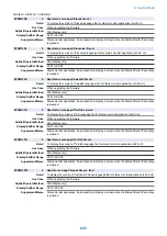
LAMP-CL
2
Dspl LED light intnsty adj VL:clr, front
Detail
To display the LED light intensity adjustment value of Scanner Unit (for front side) in color scanning
mode.
Use Case
When image failure occurs at front side scanning in color mode
Adj/Set/Operate Method
N/A (Display only)
Display/Adj/Set Range
55 to 275
Appropriate Target Value
100 - 275
Supplement/Memo
LED cannot be replaced individually. Replace the Scanner Unit.
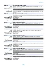
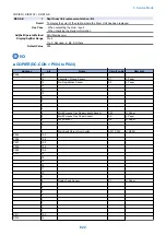
LAMP2-BW
2
Dspl LED light intnsty adj VL: B&W, back
Detail
To display the LED light intensity adjustment value of Scanner Unit (for back side) in B&W scanning
mode.
Use Case
When image failure occurs at back side scanning in black mode.
Adj/Set/Operate Method
N/A (Display only)
Display/Adj/Set Range
55 to 275
Appropriate Target Value
100 - 275
Supplement/Memo
LED cannot be replaced individually. Replace the Scanner Unit.
LAMP2-CL
2
Dspl LED light intnsty adj VL: clr, back
Detail
To display the LED light intensity adjustment value of Scanner Unit (for back side) in color scanning
mode.
Use Case
When image failure occurs at back side scanning in color mode
Adj/Set/Operate Method
N/A (Display only)
Display/Adj/Set Range
55 to 275
Appropriate Target Value
100 - 275
Supplement/Memo
LED cannot be replaced individually. Replace the Scanner Unit.
8. Service Mode
617
Summary of Contents for imagerunner advance 4551i
Page 19: ...Product Overview 1 Product Lineup 7 Features 13 Specifications 16 Name of Parts 26 ...
Page 155: ...Periodical Service 3 Consumable Parts List 143 Cleaning Check Adjustment Locations 146 ...
Page 392: ...Error Jam Alarm 7 Overview 380 Error Code 383 Jam Code 509 Alarm Code 520 ...
Page 545: ...Service Mode 8 Overview 533 COPIER 549 FEEDER 845 SORTER 851 BOARD 871 ...
Page 892: ...Unpacking 1 2 1200 mm 840 mm 769 mm 1230 mm 2430 mm 3 9 Installation 879 ...
Page 895: ...3 4 NOTE Keep the removed screws for relocating the host machine 2x 5 6 7 9 Installation 882 ...
Page 896: ...8 9 10 1x Installing the Air Filter 1 9 Installation 883 ...
Page 897: ...2 3 Installing the Drum Unit 1 2 3 9 Installation 884 ...
Page 899: ...8 NOTE The screw removed at procedure 4 is used 1x 9 10 11 12 9 Installation 886 ...
Page 923: ...5 6 NOTE Use the screws and Rubber Caps removed in step 1 2x 7 2x 9 Installation 910 ...
Page 935: ...7 1x 8 9 6x 10 2x 9 Installation 922 ...
Page 936: ...11 Installing the NFC Kit 1 2 2x 3 TP M3x4 1x 9 Installation 923 ...
Page 938: ...4 5 1x 6 9 Installation 925 ...
Page 985: ...8 2x 2x TP M4x8 Black When installing the USB Keyboard 1 9 Installation 972 ...
Page 991: ...7 4x 8 1x 1x Lower Cover 9 1x 10 1x 1x 9 Installation 978 ...
Page 992: ...11 1x 1x 12 1x 13 TP M3x12 2x 14 4x TP M3x6 9 Installation 979 ...
Page 997: ...Installation Procedure 1 2 2x 3 2x 4 6x 5 4x 9 Installation 984 ...
Page 998: ...6 7 NOTE Do not close the Wire Saddle 1x 1x 8 9 9 Installation 985 ...
Page 1003: ...2 1x 1x 3 2x 2x 4 9 Installation 990 ...
Page 1012: ...2 1x 1x 3 2x 2x 4 9 Installation 999 ...
Page 1014: ...7 CAUTION The connector must be contacted TP㸹M3x6 3x 1x 8 4x 9 9 Installation 1001 ...
Page 1016: ...13 4x 14 15 Binding M4x16 Binding M3x16 2x M3x16 M4x16 16 Binding M4x6 1x 9 Installation 1003 ...
Page 1023: ...Installation Procedure Preparation 1 4x 2 1x 1x 3 2x 9 Installation 1010 ...
Page 1029: ...4 5 1x 1x 9 Installation 1016 ...
Page 1048: ...3 2x TP M3x8 Black 4 2x TP M3x6 5 9 Installation 1035 ...
Page 1053: ... Installing the Removable HDD Kit 1 2x 2x 2 3 1x 4 9 Installation 1040 ...
Page 1065: ...3 2x TP M3x8 Black 4 2x TP M3x6 5 9 Installation 1052 ...
Page 1071: ... Installing the Removable HDD Kit 1 2x 2x 2 3 1x 4 9 Installation 1058 ...


