


Overview
It is possible to see each item of service mode so that those who access to service mode can understand how to use them.
The main types of this machine's service mode are shown below.
Points to Note when Executing Service Mode
• When setting/executing service mode, do not open/close the cover or turn off the power while "active" is displayed. Otherwise,
it may not set/execute correctly.
• Depending on the service mode, some items are listed as "Do not use this item at the normal service" in "Caution". The item
is created on the basis that it will be used in the following situations, so it must not be used for any other situations.
• When entering setting values while replacing the PCB or clearing RAM data (mentioned in "Use case")
• When there was an instruction from a service office (for reasons such as a large adverse effect or setting is difficult)
• When taking individual measures (tender business, etc.)
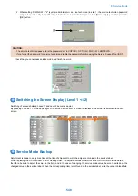
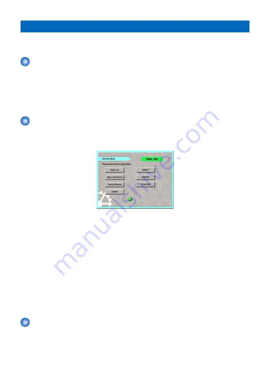
Service Mode Menu
Service mode has two mode lists: [MODELIST] and [MODELIST CLASSIC]. Press the button to display the initial screen of each
mode.
The differences between these modes are described below.
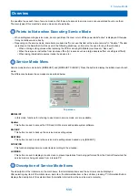
Top screen
MODELIST
In this mode, functions for referring to each item in service mode, etc. are available.
Updater
This button is used to access the CDS and UGW servers and update system software.
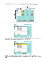
BACKUP
This button is used to back up the service mode setting values.
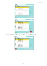
RESTORE
This button is used to restore the service mode setting values backed up by [BACKUP].
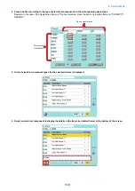
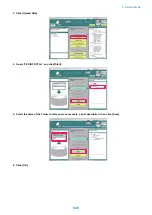
SITUATION
This function displays service mode items according to the situation.
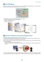
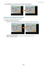
LUI MASK
This button is used to display a mask screen to prevent operations from being performed from the Control Panel while the
service mode is being accessed from a remote PC.
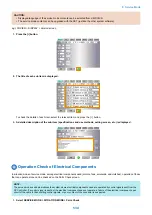
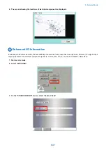
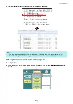
Description of Service Mode Items
The description of the initial screen, the main items, the intermediate items and the sub items can be displayed.
After selecting any item of the initial screen, main item, the intermediate item or the sub item, pressing "i" (Information Button)
displays the description of the selected item (hereinafter referred to as the service mode contents).
8. Service Mode
533
Summary of Contents for imagerunner advance 4551i
Page 19: ...Product Overview 1 Product Lineup 7 Features 13 Specifications 16 Name of Parts 26 ...
Page 155: ...Periodical Service 3 Consumable Parts List 143 Cleaning Check Adjustment Locations 146 ...
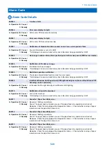
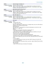
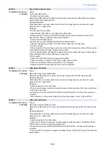
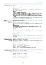
Page 392: ...Error Jam Alarm 7 Overview 380 Error Code 383 Jam Code 509 Alarm Code 520 ...
Page 545: ...Service Mode 8 Overview 533 COPIER 549 FEEDER 845 SORTER 851 BOARD 871 ...
Page 892: ...Unpacking 1 2 1200 mm 840 mm 769 mm 1230 mm 2430 mm 3 9 Installation 879 ...
Page 895: ...3 4 NOTE Keep the removed screws for relocating the host machine 2x 5 6 7 9 Installation 882 ...
Page 896: ...8 9 10 1x Installing the Air Filter 1 9 Installation 883 ...
Page 897: ...2 3 Installing the Drum Unit 1 2 3 9 Installation 884 ...
Page 899: ...8 NOTE The screw removed at procedure 4 is used 1x 9 10 11 12 9 Installation 886 ...
Page 923: ...5 6 NOTE Use the screws and Rubber Caps removed in step 1 2x 7 2x 9 Installation 910 ...
Page 935: ...7 1x 8 9 6x 10 2x 9 Installation 922 ...
Page 936: ...11 Installing the NFC Kit 1 2 2x 3 TP M3x4 1x 9 Installation 923 ...
Page 938: ...4 5 1x 6 9 Installation 925 ...
Page 985: ...8 2x 2x TP M4x8 Black When installing the USB Keyboard 1 9 Installation 972 ...
Page 991: ...7 4x 8 1x 1x Lower Cover 9 1x 10 1x 1x 9 Installation 978 ...
Page 992: ...11 1x 1x 12 1x 13 TP M3x12 2x 14 4x TP M3x6 9 Installation 979 ...
Page 997: ...Installation Procedure 1 2 2x 3 2x 4 6x 5 4x 9 Installation 984 ...
Page 998: ...6 7 NOTE Do not close the Wire Saddle 1x 1x 8 9 9 Installation 985 ...
Page 1003: ...2 1x 1x 3 2x 2x 4 9 Installation 990 ...
Page 1012: ...2 1x 1x 3 2x 2x 4 9 Installation 999 ...
Page 1014: ...7 CAUTION The connector must be contacted TP㸹M3x6 3x 1x 8 4x 9 9 Installation 1001 ...
Page 1016: ...13 4x 14 15 Binding M4x16 Binding M3x16 2x M3x16 M4x16 16 Binding M4x6 1x 9 Installation 1003 ...
Page 1023: ...Installation Procedure Preparation 1 4x 2 1x 1x 3 2x 9 Installation 1010 ...
Page 1029: ...4 5 1x 1x 9 Installation 1016 ...
Page 1048: ...3 2x TP M3x8 Black 4 2x TP M3x6 5 9 Installation 1035 ...
Page 1053: ... Installing the Removable HDD Kit 1 2x 2x 2 3 1x 4 9 Installation 1040 ...
Page 1065: ...3 2x TP M3x8 Black 4 2x TP M3x6 5 9 Installation 1052 ...
Page 1071: ... Installing the Removable HDD Kit 1 2x 2x 2 3 1x 4 9 Installation 1058 ...


