


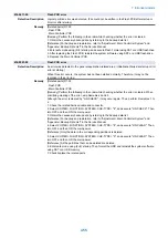

602-0801-00
HDD error
Detection Description
An error was detected in the general application-related area. (Initialization failed at startup or I/O
error at startup)
When this error occurs, the system has not been started normally. Therefore, it may not be
recorded in the error log.
Remedy
[Related parts] R1.00
- Harnesses between the Main Controller PCB and the HDD
- HDD
- Main Controller PCB
[Remedy] Perform the following in the order while checking whether the error is cleared. When
prioritizing clearing of the error, skip Remedies 2 and 3.
Although the error is cleared by "HD-CHECK", it may occur again. Thus, perform Remedies 1 to
4.
1. Check the related harness/cable and connector.
2. Select COPIER> FUNCTION> SYSTEM> CHK-TYPE> "8", and execute "HD-CHECK". Then,
turn OFF and then ON the main power.
3. Obtain the necessary backup data by referring to the backup data list.
[Reference] For backup and restoration, refer to "Adjustment> Main Controller System" and
"Appendix> Backup Data List" in the Service Manual.
4. Select COPIER> FUNCTION> SYSTEM> CHK-TYPE> "8", and execute "HD-CLEAR". Then,
turn OFF and then ON the main power.
[Reference] Only the data in the corresponding partitions is deleted.
5. Select COPIER> FUNCTION> SYSTEM> CHK-TYPE> "0", and execute "HD-CLEAR". Then,
turn OFF and then ON the main power.
[Reference] All the partitions that can be deleted are deleted.
6. Enter safe mode using (2+8) startup. Then format the HDD and reinstall the system software
using SST or a USB flash drive.
7. Check/replace the related parts.
602-0811-00
HDD error
Detection Description
An error was detected in the general application-related area. (File could not be written in the HDD
after startup or I/O error after startup)
Remedy
[Related parts] R1.00
- Harnesses between the Main Controller PCB and the HDD
- HDD
- Main Controller PCB
[Remedy] Perform the following in the order while checking whether the error is cleared. When
prioritizing clearing of the error, skip Remedies 2 and 3.
Although the error is cleared by "HD-CHECK", it may occur again. Thus, perform Remedies 1 to
4.
1. Check the related harness/cable and connector.
2. Select COPIER> FUNCTION> SYSTEM> CHK-TYPE> "8", and execute "HD-CHECK". Then,
turn OFF and then ON the main power.
3. Obtain the necessary backup data by referring to the backup data list.
[Reference] For backup and restoration, refer to "Adjustment> Main Controller System" and
"Appendix> Backup Data List" in the Service Manual.
4. Select COPIER> FUNCTION> SYSTEM> CHK-TYPE> "8", and execute "HD-CLEAR". Then,
turn OFF and then ON the main power.
[Reference] Only the data in the corresponding partitions is deleted.
5. Select COPIER> FUNCTION> SYSTEM> CHK-TYPE> "0", and execute "HD-CLEAR". Then,
turn OFF and then ON the main power.
[Reference] All the partitions that can be deleted are deleted.
6. Enter safe mode using (2+8) startup. Then format the HDD and reinstall the system software
using SST or a USB flash drive.
7. Check/replace the related parts.
7. Error/Jam/Alarm
440
Summary of Contents for imagerunner advance 4551i
Page 19: ...Product Overview 1 Product Lineup 7 Features 13 Specifications 16 Name of Parts 26 ...
Page 155: ...Periodical Service 3 Consumable Parts List 143 Cleaning Check Adjustment Locations 146 ...
Page 392: ...Error Jam Alarm 7 Overview 380 Error Code 383 Jam Code 509 Alarm Code 520 ...
Page 545: ...Service Mode 8 Overview 533 COPIER 549 FEEDER 845 SORTER 851 BOARD 871 ...
Page 892: ...Unpacking 1 2 1200 mm 840 mm 769 mm 1230 mm 2430 mm 3 9 Installation 879 ...
Page 895: ...3 4 NOTE Keep the removed screws for relocating the host machine 2x 5 6 7 9 Installation 882 ...
Page 896: ...8 9 10 1x Installing the Air Filter 1 9 Installation 883 ...
Page 897: ...2 3 Installing the Drum Unit 1 2 3 9 Installation 884 ...
Page 899: ...8 NOTE The screw removed at procedure 4 is used 1x 9 10 11 12 9 Installation 886 ...
Page 923: ...5 6 NOTE Use the screws and Rubber Caps removed in step 1 2x 7 2x 9 Installation 910 ...
Page 935: ...7 1x 8 9 6x 10 2x 9 Installation 922 ...
Page 936: ...11 Installing the NFC Kit 1 2 2x 3 TP M3x4 1x 9 Installation 923 ...
Page 938: ...4 5 1x 6 9 Installation 925 ...
Page 985: ...8 2x 2x TP M4x8 Black When installing the USB Keyboard 1 9 Installation 972 ...
Page 991: ...7 4x 8 1x 1x Lower Cover 9 1x 10 1x 1x 9 Installation 978 ...
Page 992: ...11 1x 1x 12 1x 13 TP M3x12 2x 14 4x TP M3x6 9 Installation 979 ...
Page 997: ...Installation Procedure 1 2 2x 3 2x 4 6x 5 4x 9 Installation 984 ...
Page 998: ...6 7 NOTE Do not close the Wire Saddle 1x 1x 8 9 9 Installation 985 ...
Page 1003: ...2 1x 1x 3 2x 2x 4 9 Installation 990 ...
Page 1012: ...2 1x 1x 3 2x 2x 4 9 Installation 999 ...
Page 1014: ...7 CAUTION The connector must be contacted TP㸹M3x6 3x 1x 8 4x 9 9 Installation 1001 ...
Page 1016: ...13 4x 14 15 Binding M4x16 Binding M3x16 2x M3x16 M4x16 16 Binding M4x6 1x 9 Installation 1003 ...
Page 1023: ...Installation Procedure Preparation 1 4x 2 1x 1x 3 2x 9 Installation 1010 ...
Page 1029: ...4 5 1x 1x 9 Installation 1016 ...
Page 1048: ...3 2x TP M3x8 Black 4 2x TP M3x6 5 9 Installation 1035 ...
Page 1053: ... Installing the Removable HDD Kit 1 2x 2x 2 3 1x 4 9 Installation 1040 ...
Page 1065: ...3 2x TP M3x8 Black 4 2x TP M3x6 5 9 Installation 1052 ...
Page 1071: ... Installing the Removable HDD Kit 1 2x 2x 2 3 1x 4 9 Installation 1058 ...


