

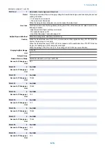


COPIER > ADJUST > FIXING
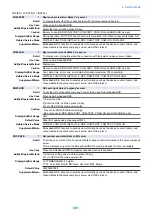
FX-FL-LW
2
Adj of fixing film speed at half speed
Detail
To adjust the fixing film speed at the half speed
Use Case
When paper passes through the registration roller, the density difference occurs by slack/tension
of the paper on the image trailing edge (about 45mm).
When executing RAM clear of DC controller PCB/replacing the PCB
Adj/Set/Operate Method
Select the item to be highlighted to enter the setting value (switch with +/- key), and then press OK
key.
Display/Adj/Set Range
-3 to 3
Unit
%
Default Value
0
Amount of Change per
Unit
1
FN-MV-SW
2
Change rotational speed: fixing cool fan
Detail
When the rotational speed for the fixing cooling fan is changed to reduce the curl amount of the
moist paper
Use Case
When the rotational speed for the fixing cooling fan shutter of the curl alleviation.
Adj/Set/Operate Method
Select the item to be highlighted to enter the setting value (switch with +/- key), and then press OK
key.
Display/Adj/Set Range
0 to 2
0: OFF, 1: Half speed, 2: Full speed
Default Value
1
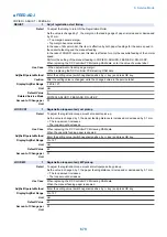
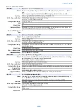
ADJ-FNSH
2
Open wid adj of fixing cool fan shutter
Detail
When the open width for the fixing cooling fan shutter is changed to reduce the curl amount of the
moist paper
As the value in changed by 1, the open width is increased or decreased by 4 mm.
+: The open width increases.
-: The open width decreases.
Use Case
When the open width for the fixing cooling fan shutter of the curl alleviation.
Adj/Set/Operate Method
Select the item to be highlighted to enter the setting value (switch with +/- key), and then press OK
key.
Display/Adj/Set Range
0 to 14
0 to 6: Open width is 0 to 24 mm (4 mm unit)
7 to 14: Open width is 30 to 58 mm (4 mm unit)
Default Value
7
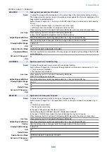
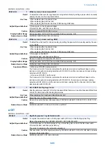
■ MISC
COPIER > ADJUST > MISC
SEG-ADJ
1
Set criteria for text/photo: front side
Detail
To set whether to judge the original scanned with the Scanner Unit (for front side) in Text/
Photo/Map mode as text or photo.
As the value is increased, the original tends to be detected as a photo document, and as the value
is decreased, the original tends to be detected as a text document.
The setting is applied to the image on the front side when the Copyboard/DADF (1-path model) is
installed, whereas it is applied to the images on both the front and back sides when the DADF
(reverse model) is installed.
Use Case
When adjusting the judgment level of text/photo original scanned with the Scanner Unit (for front
side) in Text/Photo/Map mode
Adj/Set/Operate Method
1) Enter the setting value (switch negative/positive by -/+ key) and press OK key.
2) Turn OFF/ON the main power switch.
Display/Adj/Set Range
-4 to 4
Default Value
0
8. Service Mode
684
Summary of Contents for imagerunner advance 4551i
Page 19: ...Product Overview 1 Product Lineup 7 Features 13 Specifications 16 Name of Parts 26 ...
Page 155: ...Periodical Service 3 Consumable Parts List 143 Cleaning Check Adjustment Locations 146 ...
Page 392: ...Error Jam Alarm 7 Overview 380 Error Code 383 Jam Code 509 Alarm Code 520 ...
Page 545: ...Service Mode 8 Overview 533 COPIER 549 FEEDER 845 SORTER 851 BOARD 871 ...
Page 892: ...Unpacking 1 2 1200 mm 840 mm 769 mm 1230 mm 2430 mm 3 9 Installation 879 ...
Page 895: ...3 4 NOTE Keep the removed screws for relocating the host machine 2x 5 6 7 9 Installation 882 ...
Page 896: ...8 9 10 1x Installing the Air Filter 1 9 Installation 883 ...
Page 897: ...2 3 Installing the Drum Unit 1 2 3 9 Installation 884 ...
Page 899: ...8 NOTE The screw removed at procedure 4 is used 1x 9 10 11 12 9 Installation 886 ...
Page 923: ...5 6 NOTE Use the screws and Rubber Caps removed in step 1 2x 7 2x 9 Installation 910 ...
Page 935: ...7 1x 8 9 6x 10 2x 9 Installation 922 ...
Page 936: ...11 Installing the NFC Kit 1 2 2x 3 TP M3x4 1x 9 Installation 923 ...
Page 938: ...4 5 1x 6 9 Installation 925 ...
Page 985: ...8 2x 2x TP M4x8 Black When installing the USB Keyboard 1 9 Installation 972 ...
Page 991: ...7 4x 8 1x 1x Lower Cover 9 1x 10 1x 1x 9 Installation 978 ...
Page 992: ...11 1x 1x 12 1x 13 TP M3x12 2x 14 4x TP M3x6 9 Installation 979 ...
Page 997: ...Installation Procedure 1 2 2x 3 2x 4 6x 5 4x 9 Installation 984 ...
Page 998: ...6 7 NOTE Do not close the Wire Saddle 1x 1x 8 9 9 Installation 985 ...
Page 1003: ...2 1x 1x 3 2x 2x 4 9 Installation 990 ...
Page 1012: ...2 1x 1x 3 2x 2x 4 9 Installation 999 ...
Page 1014: ...7 CAUTION The connector must be contacted TP㸹M3x6 3x 1x 8 4x 9 9 Installation 1001 ...
Page 1016: ...13 4x 14 15 Binding M4x16 Binding M3x16 2x M3x16 M4x16 16 Binding M4x6 1x 9 Installation 1003 ...
Page 1023: ...Installation Procedure Preparation 1 4x 2 1x 1x 3 2x 9 Installation 1010 ...
Page 1029: ...4 5 1x 1x 9 Installation 1016 ...
Page 1048: ...3 2x TP M3x8 Black 4 2x TP M3x6 5 9 Installation 1035 ...
Page 1053: ... Installing the Removable HDD Kit 1 2x 2x 2 3 1x 4 9 Installation 1040 ...
Page 1065: ...3 2x TP M3x8 Black 4 2x TP M3x6 5 9 Installation 1052 ...
Page 1071: ... Installing the Removable HDD Kit 1 2x 2x 2 3 1x 4 9 Installation 1058 ...


