


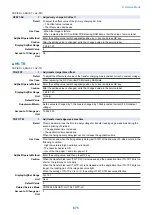


COPIER > ADJUST > FEED-ADJ
LOOP-ENV
2
Reg loop amnt adj: cst feed of envlp
Detail
To adjust the registration loop amount at cassette pickup of envelope.
As the value in changed by 1, the paper feeding distance is increased or decreased by 0.1 mm.
+: The loop amount increases.
-: The loop amount decreases.
Use Case
When the envelope is skewed at the cassette feeding
Adj/Set/Operate Method
Enter the setting value (switch negative/positive by -/+ key) and press OK key.
Display/Adj/Set Range
-128 to 127
Unit
mm
Default Value
0
Amount of Change per
Unit
0.1
ADJ-PTMG
2
Feed timing Adj
Detail
To adjust the paper feeding timing according to the feed allowance temperature. (regardless of
the fixing mode)
As the value in changed by 1, the feed allowance temperature is increased or decreased by 3
degrees centigrade.
+: The feed allowance temperature decreases.
-: The feed allowance temperature increases.
Use Case
Use to shorten the first copy time or the warm up time.
Adj/Set/Operate Method
Enter the setting value (switch negative/positive by -/+ key) and press OK key.
Display/Adj/Set Range
0 to 14
0 to 2: +15 deg C
3 to 11: each 3 deg C
12 to 14: -15 deg C
Default Value
7
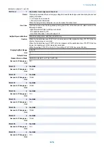
■ CST-ADJ
COPIER > ADJUST > CST-ADJ
MF-A4R
1
Adj of MP Tray A4R paper width
Detail
To adjust the width of A4R paper in the Multi-purpose Tray.
When replacing the DC Controller PCB/clearing RAM data, enter the value of service label.
When replacing the Multi-purpose Tray Paper Width Detection PCB or registering a new value,
execute COPIER> FUNCTION> CST> MF-A4R.
Use Case
- When replacing the DC Controller PCB/clearing RAM data
- When replacing the Multi-purpose Tray Paper Width Detection PCB or registering a new value
Adj/Set/Operate Method
Enter the setting value, and then press OK key.
Caution
After the setting value is changed, write the changed value in the service label.
Display/Adj/Set Range
0 to 1024
Default Value
359
Related Service Mode
COPIER> FUNCTION> CST> MF-A4R
8. Service Mode
682
Summary of Contents for imagerunner advance 4551i
Page 19: ...Product Overview 1 Product Lineup 7 Features 13 Specifications 16 Name of Parts 26 ...
Page 155: ...Periodical Service 3 Consumable Parts List 143 Cleaning Check Adjustment Locations 146 ...
Page 392: ...Error Jam Alarm 7 Overview 380 Error Code 383 Jam Code 509 Alarm Code 520 ...
Page 545: ...Service Mode 8 Overview 533 COPIER 549 FEEDER 845 SORTER 851 BOARD 871 ...
Page 892: ...Unpacking 1 2 1200 mm 840 mm 769 mm 1230 mm 2430 mm 3 9 Installation 879 ...
Page 895: ...3 4 NOTE Keep the removed screws for relocating the host machine 2x 5 6 7 9 Installation 882 ...
Page 896: ...8 9 10 1x Installing the Air Filter 1 9 Installation 883 ...
Page 897: ...2 3 Installing the Drum Unit 1 2 3 9 Installation 884 ...
Page 899: ...8 NOTE The screw removed at procedure 4 is used 1x 9 10 11 12 9 Installation 886 ...
Page 923: ...5 6 NOTE Use the screws and Rubber Caps removed in step 1 2x 7 2x 9 Installation 910 ...
Page 935: ...7 1x 8 9 6x 10 2x 9 Installation 922 ...
Page 936: ...11 Installing the NFC Kit 1 2 2x 3 TP M3x4 1x 9 Installation 923 ...
Page 938: ...4 5 1x 6 9 Installation 925 ...
Page 985: ...8 2x 2x TP M4x8 Black When installing the USB Keyboard 1 9 Installation 972 ...
Page 991: ...7 4x 8 1x 1x Lower Cover 9 1x 10 1x 1x 9 Installation 978 ...
Page 992: ...11 1x 1x 12 1x 13 TP M3x12 2x 14 4x TP M3x6 9 Installation 979 ...
Page 997: ...Installation Procedure 1 2 2x 3 2x 4 6x 5 4x 9 Installation 984 ...
Page 998: ...6 7 NOTE Do not close the Wire Saddle 1x 1x 8 9 9 Installation 985 ...
Page 1003: ...2 1x 1x 3 2x 2x 4 9 Installation 990 ...
Page 1012: ...2 1x 1x 3 2x 2x 4 9 Installation 999 ...
Page 1014: ...7 CAUTION The connector must be contacted TP㸹M3x6 3x 1x 8 4x 9 9 Installation 1001 ...
Page 1016: ...13 4x 14 15 Binding M4x16 Binding M3x16 2x M3x16 M4x16 16 Binding M4x6 1x 9 Installation 1003 ...
Page 1023: ...Installation Procedure Preparation 1 4x 2 1x 1x 3 2x 9 Installation 1010 ...
Page 1029: ...4 5 1x 1x 9 Installation 1016 ...
Page 1048: ...3 2x TP M3x8 Black 4 2x TP M3x6 5 9 Installation 1035 ...
Page 1053: ... Installing the Removable HDD Kit 1 2x 2x 2 3 1x 4 9 Installation 1040 ...
Page 1065: ...3 2x TP M3x8 Black 4 2x TP M3x6 5 9 Installation 1052 ...
Page 1071: ... Installing the Removable HDD Kit 1 2x 2x 2 3 1x 4 9 Installation 1058 ...


