


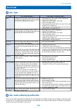


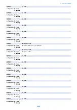

ACC ID
Jam Code
Type
Sensor Name/Description
Sensor ID
02
1001
DELAY
Inlet Sensor
PS101
02
1002
DELAY
Delivery Sensor
PS102
02
1003
DELAY
Buffer Sensor
PS103
02
1004
DELAY
Lower Escape Delivery Sensor
PS111
02
1008
DELAY
Saddle Delivery Sensor
PS203
02
1009
DELAY
Saddle Inlet Sensor
PS201
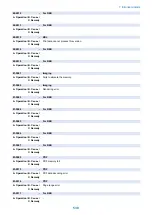
02
1101
STNRY
Inlet Sensor
PS101
02
1102
STNRY
Delivery Sensor
PS102
02
1103
STNRY
Buffer Sensor
PS103
02
1104
STNRY
Lower Escape Delivery Sensor
PS111
02
1108
STNRY
Saddle Delivery Sensor
PS203
02
1109
STNRY
Saddle Inlet Sensor
PS201
02
1200
OTHER
-
-
02
1301
POWER ON
Inlet Sensor
PS101
02
1302
POWER ON
Delivery Sensor
PS102
02
1303
POWER ON
Buffer Sensor
PS103
02
1304
POWER ON
Lower Escape Delivery Sensor
PS111
02
1307
POWER ON
Saddle Processing Tray Paper
Sensor
PS202
02
1308
POWER ON
Saddle Delivery Sensor
PS203
02
1309
POWER ON
Saddle Inlet Sensor
PS201
02
1400
COVER OP
-
PS104,SW101/MSW1
02
1500
STAPLE
-
-
02
1501
SDL STP
-
PS215
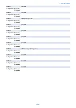
02
1801
ERROR
Staple-free Binding
PS130
02
1802
ERROR
Staple-free Binding HP Sensor
PS129
02
1803
ERROR
-
-
02
1804
ERROR
-
-
02
1805
ERROR
-
-
02
1C14
ERROR
-
-
02
1C30
ERROR
-
-
02
1C32
ERROR
-
-
02
1C35
ERROR
-
-
02
1C37
ERROR
-
-
02
1C40
ERROR
-
-
02
1C77
ERROR
-
-
02
1C53
ERROR
-
-
02
1C54
ERROR
-
-
02
1C78
ERROR
-
-
02
1C7B
ERROR
-
-
02
1C83
ERROR
-
-
02
1CF0
ERROR
-
-
02
1CF1
ERROR
-
-
02
1CF3
ERROR
-
-
02
1CF6
ERROR
-
-
02
1CF8
ERROR
-
-
02
1CFA
ERROR
-
-
02
1F01
OTHER
-
-
02
1F32
OTHER
-
-
02
1F90
SEQUENCE
-
-
7. Error/Jam/Alarm
516
Summary of Contents for imagerunner advance 4551i
Page 19: ...Product Overview 1 Product Lineup 7 Features 13 Specifications 16 Name of Parts 26 ...
Page 155: ...Periodical Service 3 Consumable Parts List 143 Cleaning Check Adjustment Locations 146 ...
Page 392: ...Error Jam Alarm 7 Overview 380 Error Code 383 Jam Code 509 Alarm Code 520 ...
Page 545: ...Service Mode 8 Overview 533 COPIER 549 FEEDER 845 SORTER 851 BOARD 871 ...
Page 892: ...Unpacking 1 2 1200 mm 840 mm 769 mm 1230 mm 2430 mm 3 9 Installation 879 ...
Page 895: ...3 4 NOTE Keep the removed screws for relocating the host machine 2x 5 6 7 9 Installation 882 ...
Page 896: ...8 9 10 1x Installing the Air Filter 1 9 Installation 883 ...
Page 897: ...2 3 Installing the Drum Unit 1 2 3 9 Installation 884 ...
Page 899: ...8 NOTE The screw removed at procedure 4 is used 1x 9 10 11 12 9 Installation 886 ...
Page 923: ...5 6 NOTE Use the screws and Rubber Caps removed in step 1 2x 7 2x 9 Installation 910 ...
Page 935: ...7 1x 8 9 6x 10 2x 9 Installation 922 ...
Page 936: ...11 Installing the NFC Kit 1 2 2x 3 TP M3x4 1x 9 Installation 923 ...
Page 938: ...4 5 1x 6 9 Installation 925 ...
Page 985: ...8 2x 2x TP M4x8 Black When installing the USB Keyboard 1 9 Installation 972 ...
Page 991: ...7 4x 8 1x 1x Lower Cover 9 1x 10 1x 1x 9 Installation 978 ...
Page 992: ...11 1x 1x 12 1x 13 TP M3x12 2x 14 4x TP M3x6 9 Installation 979 ...
Page 997: ...Installation Procedure 1 2 2x 3 2x 4 6x 5 4x 9 Installation 984 ...
Page 998: ...6 7 NOTE Do not close the Wire Saddle 1x 1x 8 9 9 Installation 985 ...
Page 1003: ...2 1x 1x 3 2x 2x 4 9 Installation 990 ...
Page 1012: ...2 1x 1x 3 2x 2x 4 9 Installation 999 ...
Page 1014: ...7 CAUTION The connector must be contacted TP㸹M3x6 3x 1x 8 4x 9 9 Installation 1001 ...
Page 1016: ...13 4x 14 15 Binding M4x16 Binding M3x16 2x M3x16 M4x16 16 Binding M4x6 1x 9 Installation 1003 ...
Page 1023: ...Installation Procedure Preparation 1 4x 2 1x 1x 3 2x 9 Installation 1010 ...
Page 1029: ...4 5 1x 1x 9 Installation 1016 ...
Page 1048: ...3 2x TP M3x8 Black 4 2x TP M3x6 5 9 Installation 1035 ...
Page 1053: ... Installing the Removable HDD Kit 1 2x 2x 2 3 1x 4 9 Installation 1040 ...
Page 1065: ...3 2x TP M3x8 Black 4 2x TP M3x6 5 9 Installation 1052 ...
Page 1071: ... Installing the Removable HDD Kit 1 2x 2x 2 3 1x 4 9 Installation 1058 ...


