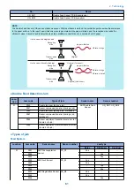


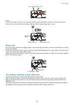

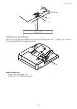


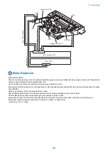

Pickup clutch(CL1)
Pickup motor(M1)
Stopper
Stopper
Document
Pickup roller
Separation roller
Feed roller
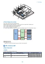
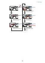
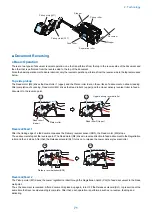
■ Document Reversing
● Basic Operation
There are two types of document reversal operation: one that is performed from the top to the reverse side of the document and
the other that is performed from the reverse side to the top of the document.
Since the basic operation methods are identical, only the reversal operation performed from the reverse side to the top is discussed
below.
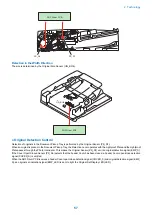
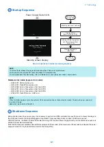
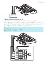
Top side pickup
The Read motor (M2) drives the Read roller 1 (upper) and the Platen roller to scan the surface of a document on stream reading.
After completion of scanning, Read motor (M2) drives the Read roller 2 (upper) and the Upper delivery reversal roller to feed a
document to the reverse point.
Upper delivery reversal roller
Platen roller
Read roller 2(Upper)
Read roller 1
(Upper)
M2
M2
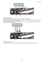
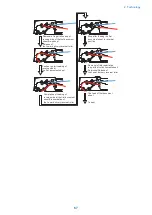
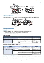
Reversal/Feed 1
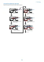
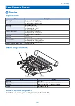
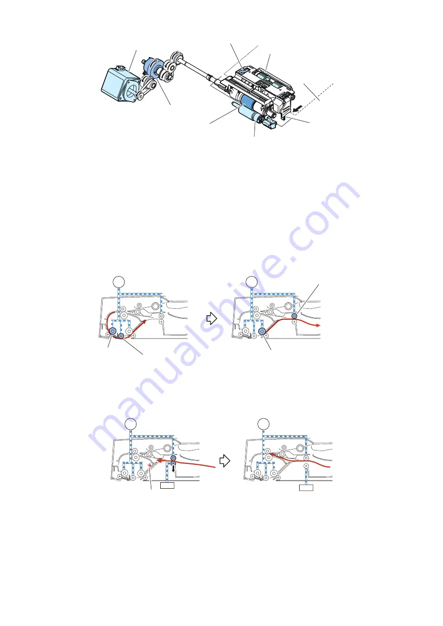
After the trailing edge of a fed document passes the Delivery reversal sensor (SR3), the Read motor (M2) stops.
Thus a document stops at the reverse point. The Read motor (M2) drives in reverse direction to feed a document to the Registration
roller and then it stops. After that, the Release solenoid (SL1) turns on to release the Lower delivery reversal roller.
Delivery reversal sensor(SR3)
SL1
M2
SL1
M2
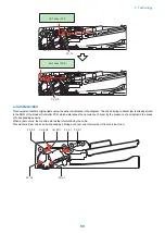
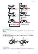
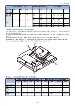
Reversal/Feed 2
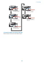
The Pickup motor (M1) drives the Lower registration roller through the Registration clutch (CL2) to feed a document to the Read
wait point.
Thus, the document is reversed. After a document is picked up again, turn OFF the Release solenoid (SL1) to pressurize at the
same time that reverse side reading is complete. After that, each operation is performed such as re-reverse, feeding and
delivering.
2. Technology
71
Summary of Contents for imagerunner advance 4551i
Page 19: ...Product Overview 1 Product Lineup 7 Features 13 Specifications 16 Name of Parts 26 ...
Page 155: ...Periodical Service 3 Consumable Parts List 143 Cleaning Check Adjustment Locations 146 ...
Page 392: ...Error Jam Alarm 7 Overview 380 Error Code 383 Jam Code 509 Alarm Code 520 ...
Page 545: ...Service Mode 8 Overview 533 COPIER 549 FEEDER 845 SORTER 851 BOARD 871 ...
Page 892: ...Unpacking 1 2 1200 mm 840 mm 769 mm 1230 mm 2430 mm 3 9 Installation 879 ...
Page 895: ...3 4 NOTE Keep the removed screws for relocating the host machine 2x 5 6 7 9 Installation 882 ...
Page 896: ...8 9 10 1x Installing the Air Filter 1 9 Installation 883 ...
Page 897: ...2 3 Installing the Drum Unit 1 2 3 9 Installation 884 ...
Page 899: ...8 NOTE The screw removed at procedure 4 is used 1x 9 10 11 12 9 Installation 886 ...
Page 923: ...5 6 NOTE Use the screws and Rubber Caps removed in step 1 2x 7 2x 9 Installation 910 ...
Page 935: ...7 1x 8 9 6x 10 2x 9 Installation 922 ...
Page 936: ...11 Installing the NFC Kit 1 2 2x 3 TP M3x4 1x 9 Installation 923 ...
Page 938: ...4 5 1x 6 9 Installation 925 ...
Page 985: ...8 2x 2x TP M4x8 Black When installing the USB Keyboard 1 9 Installation 972 ...
Page 991: ...7 4x 8 1x 1x Lower Cover 9 1x 10 1x 1x 9 Installation 978 ...
Page 992: ...11 1x 1x 12 1x 13 TP M3x12 2x 14 4x TP M3x6 9 Installation 979 ...
Page 997: ...Installation Procedure 1 2 2x 3 2x 4 6x 5 4x 9 Installation 984 ...
Page 998: ...6 7 NOTE Do not close the Wire Saddle 1x 1x 8 9 9 Installation 985 ...
Page 1003: ...2 1x 1x 3 2x 2x 4 9 Installation 990 ...
Page 1012: ...2 1x 1x 3 2x 2x 4 9 Installation 999 ...
Page 1014: ...7 CAUTION The connector must be contacted TP㸹M3x6 3x 1x 8 4x 9 9 Installation 1001 ...
Page 1016: ...13 4x 14 15 Binding M4x16 Binding M3x16 2x M3x16 M4x16 16 Binding M4x6 1x 9 Installation 1003 ...
Page 1023: ...Installation Procedure Preparation 1 4x 2 1x 1x 3 2x 9 Installation 1010 ...
Page 1029: ...4 5 1x 1x 9 Installation 1016 ...
Page 1048: ...3 2x TP M3x8 Black 4 2x TP M3x6 5 9 Installation 1035 ...
Page 1053: ... Installing the Removable HDD Kit 1 2x 2x 2 3 1x 4 9 Installation 1040 ...
Page 1065: ...3 2x TP M3x8 Black 4 2x TP M3x6 5 9 Installation 1052 ...
Page 1071: ... Installing the Removable HDD Kit 1 2x 2x 2 3 1x 4 9 Installation 1058 ...


