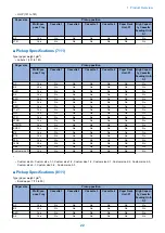


Item
Specification/Function
Remarks
Magnification ratio
25% to 400%
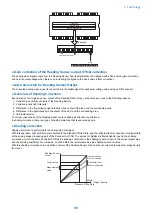
Black & White: Scan magnification (skipping of 2 ver-
tical lines: 25% to 50%)
Color: Digital variable magnification
Horizontal scanning direction
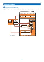
Image processing by the Main Controller PCB
Vertical scanning direction
Image processing by the Main Controller PCB
Horizontal scanning direction
-
Vertical scanning direction
Partially processed by the Reader Controller
PCB
Number of lines of the
Reading Sensor
4 lines (R, G, B, B/W)
-
Original size detection
Horizontal scanning direction
Detection by the Reading Sensor (Scanner Unit)
Vertical scanning direction
Detection by the Reflection Sensor (Original Size
Sensor 1 (AB configuration) or Original Size Sen-
sor 2 (Inch configuration))
-
Maximum document
size
At copyboard reading
297 mm x 431.8 mm
When using the ADF
304.8 mm x 630 mm
-
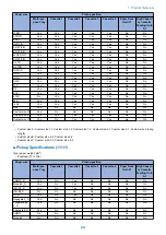
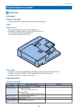
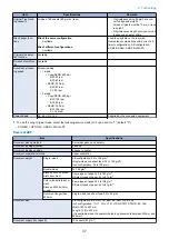
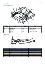
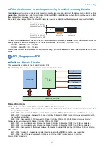
● ADF
Single pass ADF
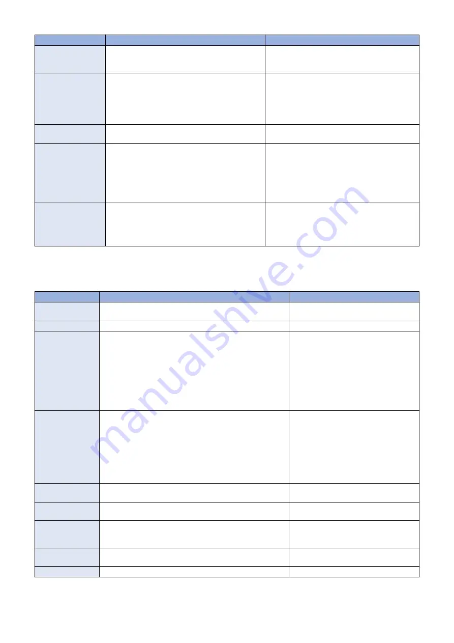
Item
Specifications
Remarks
Document pickup
method
Automatic pickup/delivery method
Simultaneous duplex reading
Original Type
Sheet document
-
Original basis weight
1-sided
• A/B: 38 to 157 g/m2
• Inch: 50 to 157 g/m2
2-sided
50 to 157 g/m2
Color original
64 to 157 g/m2
1-sided
• A/B: For originals 38 g/m2 or more
and less than 42 g/m2, width 257
mm (B5 size) or more and 1-sided
single sheet delivery
• A/B: For originals exceeding 432
mm,
1-sided single sheet feed:
60 to 90 g/m2
Original size
A3, A4, A4R, A5, A5R, B4, B5, B5R, B6R, LDR, LGL, LTR, LTRR,
STMT, STMTR, 8K, 16K, 16KR
Feed direction
139.7 to 432 mm (STMT to 17 inch) *432 to 630 mm originals
can also be read (see the note).
Width direction
128 to 304.8 mm (B6R to 12 inch)
• B6 paper can only be fed with landscape
orientation
• Since originals that are 432 to 630 mm
in the feed direction are larger than the
Document Pickup Tray, they can be
read while being held by the user.
Original setting direc-
tion
Pickup from the Original Tray: Face up
-
Original setting posi-
tion
Pickup from the Original Tray: Center reference
-
Document scanning
method
Stream reading
Simultaneous duplex reading can only be
performed on originals that are 432 mm or
smaller
Original separation
method
Drive-free retard separation
-
Original feed mode
1-sided, 2-sided (simultaneous)
-
2. Technology
36
Summary of Contents for imagerunner advance 4551i
Page 19: ...Product Overview 1 Product Lineup 7 Features 13 Specifications 16 Name of Parts 26 ...
Page 155: ...Periodical Service 3 Consumable Parts List 143 Cleaning Check Adjustment Locations 146 ...
Page 392: ...Error Jam Alarm 7 Overview 380 Error Code 383 Jam Code 509 Alarm Code 520 ...
Page 545: ...Service Mode 8 Overview 533 COPIER 549 FEEDER 845 SORTER 851 BOARD 871 ...
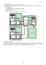
Page 892: ...Unpacking 1 2 1200 mm 840 mm 769 mm 1230 mm 2430 mm 3 9 Installation 879 ...
Page 895: ...3 4 NOTE Keep the removed screws for relocating the host machine 2x 5 6 7 9 Installation 882 ...
Page 896: ...8 9 10 1x Installing the Air Filter 1 9 Installation 883 ...
Page 897: ...2 3 Installing the Drum Unit 1 2 3 9 Installation 884 ...
Page 899: ...8 NOTE The screw removed at procedure 4 is used 1x 9 10 11 12 9 Installation 886 ...
Page 923: ...5 6 NOTE Use the screws and Rubber Caps removed in step 1 2x 7 2x 9 Installation 910 ...
Page 935: ...7 1x 8 9 6x 10 2x 9 Installation 922 ...
Page 936: ...11 Installing the NFC Kit 1 2 2x 3 TP M3x4 1x 9 Installation 923 ...
Page 938: ...4 5 1x 6 9 Installation 925 ...
Page 985: ...8 2x 2x TP M4x8 Black When installing the USB Keyboard 1 9 Installation 972 ...
Page 991: ...7 4x 8 1x 1x Lower Cover 9 1x 10 1x 1x 9 Installation 978 ...
Page 992: ...11 1x 1x 12 1x 13 TP M3x12 2x 14 4x TP M3x6 9 Installation 979 ...
Page 997: ...Installation Procedure 1 2 2x 3 2x 4 6x 5 4x 9 Installation 984 ...
Page 998: ...6 7 NOTE Do not close the Wire Saddle 1x 1x 8 9 9 Installation 985 ...
Page 1003: ...2 1x 1x 3 2x 2x 4 9 Installation 990 ...
Page 1012: ...2 1x 1x 3 2x 2x 4 9 Installation 999 ...
Page 1014: ...7 CAUTION The connector must be contacted TP㸹M3x6 3x 1x 8 4x 9 9 Installation 1001 ...
Page 1016: ...13 4x 14 15 Binding M4x16 Binding M3x16 2x M3x16 M4x16 16 Binding M4x6 1x 9 Installation 1003 ...
Page 1023: ...Installation Procedure Preparation 1 4x 2 1x 1x 3 2x 9 Installation 1010 ...
Page 1029: ...4 5 1x 1x 9 Installation 1016 ...
Page 1048: ...3 2x TP M3x8 Black 4 2x TP M3x6 5 9 Installation 1035 ...
Page 1053: ... Installing the Removable HDD Kit 1 2x 2x 2 3 1x 4 9 Installation 1040 ...
Page 1065: ...3 2x TP M3x8 Black 4 2x TP M3x6 5 9 Installation 1052 ...
Page 1071: ... Installing the Removable HDD Kit 1 2x 2x 2 3 1x 4 9 Installation 1058 ...


