


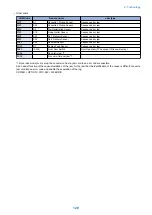

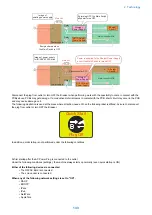
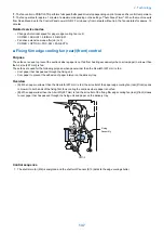


Sleep 1
The state that the controller's all-night and non-all-night power is supplied while the Control Panel is off.
When "High" is set in Settings/Registration > Preferences > Timer/Energy Settings > Sleep Mode Energy Use, the mode is shifted
from Sleep Standby during sleep.
The mode is shifted to Sleep Standby when a job is submitted during this mode, and is shifted to Standby when the Energy Saver
key is pressed.
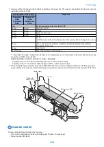
Sleep 1 (when [Consider Network Connection] is enabled)
The state that only all-night power (5 V) is supplied to the printer/scanner/controller while the Control Panel is off. Select for
responding to requests for exiting Sleep from external sources such as faxes or the network.
The mode is shifted to Sleep Standby when a job is submitted during this mode, and is shifted to Standby when the Energy Saver
key is pressed.
CAUTION:
When Settings/Registration > Preferences > Timer/Energy Settings > Sleep Mode Energy Use > Low > Consider Network
Connection > ON, the mode is shifted to this mode.
When connecting 2-line Fax or coin vendors, a shift to this mode will not take place.
When this mode is enabled, the mode is not shifted to Deep Sleep mode.
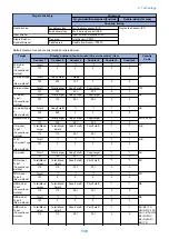
Sleep Exit
When recovering to Standby from Sleep, the machine first enters this mode. The state in which power supply is maintained for
recovery from Sleep.
Deep Sleep
In this state, the Control Panel is off while only all-night power supply (5 V) is supplied.
During sleep, the mode is shifted to this mode from Sleep Standby.
The mode is shifted to Sleep Standby when a job is submitted during this mode, and goes through Sleep Exit and is shifting to
Standby when the Energy Saver key is pressed.
When any of the following "Conditions for Not Entering Deep Sleep" applies, transition to this mode does not occur.
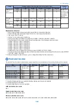
■ Conditions for Not Entering Deep Sleep
The moment the host machine enters sleep mode, the back light of the Control Panel is turned OFF. By pressing the Energy
Saver Switch, the device returns from sleep mode and the back light of the Control Panel is turned ON.
Entering auto sleep mode is prohibited when the host machine is in one of the following conditions.
Settings in Settings/Registration
• Preferences > Timer/Energy Settings
Sleep Mode Energy Use > High.
During the time set in [Auto Sleep Time]
• Preferences > Network
TCP/IP Settings > IP Address Settings > Auto IP > ON
TCP/IP Settings > DNS Settings > mDNS Settings > ON
AppleTalk Settings > Use AppleTalk > ON
IEEE 802.1X Settings > Use IEEE 802.1X > ON
• Function Settings
Fax Settings > Select RX Mode > Fax/Tel (Auto Switch)
Fax Settings > Remote RX > ON
Time is specified in [Receive/Firwird > Common Settings > Set Fax/I-Fax Inbox > Memory Lock Start Time / Memory
Lock End Time] (*1)
• Function Settings > Send
Send > Common Settings > Communication Management Report > Specify Print Time > ON (*1)
Send > Fax Settings > Modem Dial-in Settings > Set Line > Line 1 to 4 > ON.
Send > Fax Settings > Fax Activity Report > Specify Print Time > ON (*1)
10 minutes or less is specified in [Send > E-Mail/I-Fax Settings > Communication Settings > Next > POP Interval] (except
when the interval is set to "0")
Hardware status
• The Serial Coin Vendor is connected.
• The iSlot Extension Card is connected.
• The device is connected to a USB host.
2. Technology
131
Summary of Contents for imagerunner advance 4551i
Page 19: ...Product Overview 1 Product Lineup 7 Features 13 Specifications 16 Name of Parts 26 ...
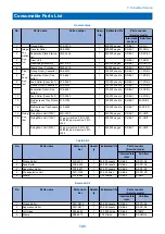
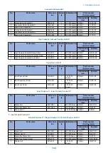
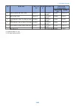
Page 155: ...Periodical Service 3 Consumable Parts List 143 Cleaning Check Adjustment Locations 146 ...
Page 392: ...Error Jam Alarm 7 Overview 380 Error Code 383 Jam Code 509 Alarm Code 520 ...
Page 545: ...Service Mode 8 Overview 533 COPIER 549 FEEDER 845 SORTER 851 BOARD 871 ...
Page 892: ...Unpacking 1 2 1200 mm 840 mm 769 mm 1230 mm 2430 mm 3 9 Installation 879 ...
Page 895: ...3 4 NOTE Keep the removed screws for relocating the host machine 2x 5 6 7 9 Installation 882 ...
Page 896: ...8 9 10 1x Installing the Air Filter 1 9 Installation 883 ...
Page 897: ...2 3 Installing the Drum Unit 1 2 3 9 Installation 884 ...
Page 899: ...8 NOTE The screw removed at procedure 4 is used 1x 9 10 11 12 9 Installation 886 ...
Page 923: ...5 6 NOTE Use the screws and Rubber Caps removed in step 1 2x 7 2x 9 Installation 910 ...
Page 935: ...7 1x 8 9 6x 10 2x 9 Installation 922 ...
Page 936: ...11 Installing the NFC Kit 1 2 2x 3 TP M3x4 1x 9 Installation 923 ...
Page 938: ...4 5 1x 6 9 Installation 925 ...
Page 985: ...8 2x 2x TP M4x8 Black When installing the USB Keyboard 1 9 Installation 972 ...
Page 991: ...7 4x 8 1x 1x Lower Cover 9 1x 10 1x 1x 9 Installation 978 ...
Page 992: ...11 1x 1x 12 1x 13 TP M3x12 2x 14 4x TP M3x6 9 Installation 979 ...
Page 997: ...Installation Procedure 1 2 2x 3 2x 4 6x 5 4x 9 Installation 984 ...
Page 998: ...6 7 NOTE Do not close the Wire Saddle 1x 1x 8 9 9 Installation 985 ...
Page 1003: ...2 1x 1x 3 2x 2x 4 9 Installation 990 ...
Page 1012: ...2 1x 1x 3 2x 2x 4 9 Installation 999 ...
Page 1014: ...7 CAUTION The connector must be contacted TP㸹M3x6 3x 1x 8 4x 9 9 Installation 1001 ...
Page 1016: ...13 4x 14 15 Binding M4x16 Binding M3x16 2x M3x16 M4x16 16 Binding M4x6 1x 9 Installation 1003 ...
Page 1023: ...Installation Procedure Preparation 1 4x 2 1x 1x 3 2x 9 Installation 1010 ...
Page 1029: ...4 5 1x 1x 9 Installation 1016 ...
Page 1048: ...3 2x TP M3x8 Black 4 2x TP M3x6 5 9 Installation 1035 ...
Page 1053: ... Installing the Removable HDD Kit 1 2x 2x 2 3 1x 4 9 Installation 1040 ...
Page 1065: ...3 2x TP M3x8 Black 4 2x TP M3x6 5 9 Installation 1052 ...
Page 1071: ... Installing the Removable HDD Kit 1 2x 2x 2 3 1x 4 9 Installation 1058 ...


