


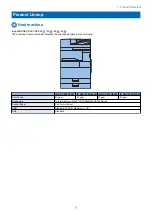
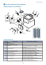


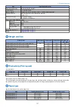


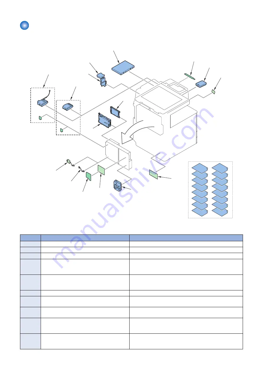
Function Expansion System Options
■ Required Options and Conditions
[2]
[3]
[4]
[9],[10]
[5]
[6]
[19]
[20]
[7]
[8]
[11],[12]
[13],[14]
[15],[16]
[17],[18]
Licence option
[1]
[21]
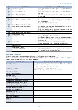
● Hardware Products
No.
Product name
Required options, conditions, etc.
[1]
NFC Kit-C1
[2]
IC Card Reader Box-C1
[3]
Connection Kit-A1 for Bluetooth LE
[4]
Utility Tray-B1
Using with Voice Operation Kit-D1 is not available.
A tray for placing originals which can be installed on the right side of
the machine.
[5]
Copy Card Reader-F1
Copy Card Reader Attachment-B5 is required.
Using with Serial Interface Kit-K3 is not available.
Using with Copy Control Interface Kit-A1 is not available.
[6]
Copy Card Reader Attachment-B5
Required when Card Reader-F1 is installed.
[7]
Serial Interface Kit-K3
Using with Copy Card Reader-F1 is not available.
Using with Copy Control Interface Kit-A1 is not available.
[8]
Copy Control Interface Kit-A1
Using with Serial Interface Kit-K3 is not available.
Using with Copy Card Reader-F1 is not available.
[9]
2.5inch/250GB HDD-N1
This is used when the mirroring function is used with Removable
HDD Kit-AL1 or HDD Mirroring Kit-J1.
No particular options and conditions are required.
[10]
2.5inch/1TB HDD-P1
This is used when the mirroring function is used with Removable
HDD Kit-AL1 or HDD Mirroring Kit-J1.
No particular options and conditions are required.
1. Product Overview
10
Summary of Contents for imagerunner advance 4551i
Page 19: ...Product Overview 1 Product Lineup 7 Features 13 Specifications 16 Name of Parts 26 ...
Page 155: ...Periodical Service 3 Consumable Parts List 143 Cleaning Check Adjustment Locations 146 ...
Page 392: ...Error Jam Alarm 7 Overview 380 Error Code 383 Jam Code 509 Alarm Code 520 ...
Page 545: ...Service Mode 8 Overview 533 COPIER 549 FEEDER 845 SORTER 851 BOARD 871 ...
Page 892: ...Unpacking 1 2 1200 mm 840 mm 769 mm 1230 mm 2430 mm 3 9 Installation 879 ...
Page 895: ...3 4 NOTE Keep the removed screws for relocating the host machine 2x 5 6 7 9 Installation 882 ...
Page 896: ...8 9 10 1x Installing the Air Filter 1 9 Installation 883 ...
Page 897: ...2 3 Installing the Drum Unit 1 2 3 9 Installation 884 ...
Page 899: ...8 NOTE The screw removed at procedure 4 is used 1x 9 10 11 12 9 Installation 886 ...
Page 923: ...5 6 NOTE Use the screws and Rubber Caps removed in step 1 2x 7 2x 9 Installation 910 ...
Page 935: ...7 1x 8 9 6x 10 2x 9 Installation 922 ...
Page 936: ...11 Installing the NFC Kit 1 2 2x 3 TP M3x4 1x 9 Installation 923 ...
Page 938: ...4 5 1x 6 9 Installation 925 ...
Page 985: ...8 2x 2x TP M4x8 Black When installing the USB Keyboard 1 9 Installation 972 ...
Page 991: ...7 4x 8 1x 1x Lower Cover 9 1x 10 1x 1x 9 Installation 978 ...
Page 992: ...11 1x 1x 12 1x 13 TP M3x12 2x 14 4x TP M3x6 9 Installation 979 ...
Page 997: ...Installation Procedure 1 2 2x 3 2x 4 6x 5 4x 9 Installation 984 ...
Page 998: ...6 7 NOTE Do not close the Wire Saddle 1x 1x 8 9 9 Installation 985 ...
Page 1003: ...2 1x 1x 3 2x 2x 4 9 Installation 990 ...
Page 1012: ...2 1x 1x 3 2x 2x 4 9 Installation 999 ...
Page 1014: ...7 CAUTION The connector must be contacted TP㸹M3x6 3x 1x 8 4x 9 9 Installation 1001 ...
Page 1016: ...13 4x 14 15 Binding M4x16 Binding M3x16 2x M3x16 M4x16 16 Binding M4x6 1x 9 Installation 1003 ...
Page 1023: ...Installation Procedure Preparation 1 4x 2 1x 1x 3 2x 9 Installation 1010 ...
Page 1029: ...4 5 1x 1x 9 Installation 1016 ...
Page 1048: ...3 2x TP M3x8 Black 4 2x TP M3x6 5 9 Installation 1035 ...
Page 1053: ... Installing the Removable HDD Kit 1 2x 2x 2 3 1x 4 9 Installation 1040 ...
Page 1065: ...3 2x TP M3x8 Black 4 2x TP M3x6 5 9 Installation 1052 ...
Page 1071: ... Installing the Removable HDD Kit 1 2x 2x 2 3 1x 4 9 Installation 1058 ...


