


• When backup is not performed normally
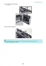
Enter the values written on the service label (on the back of the Reader Front Cover) to the following service mode
items.
Service Mode > COPIER > ADJUST > ADJ-XY
Service Mode > COPIER > ADJUST > CCD
Service Mode > COPIER > ADJUST > PASCAL >
Service Mode > FEEDER > ADJUST >
List of Items to Enter the Values of Service Label
Path for Service Modes
Service Mode Items
COPIER > ADJUST > ADJ-
XY >
ADJ-Y-DF, ADJ-X-MG, ADJY-DF2, ADJ-Y, STRD-POS
COPIER > ADJUST > CCD
>
W-PLT-X, DFTBK-R, DFCH2G2, DFCH-B10, W-PLT-Y, DFTBK-G, DFCH2G10, DFCH-G2, W-
PLT-Z, DFTBK-B, DFCH2K2, DFCH-G10, SH-TRGT, DFTBK-BW, DFCH2K10, DFCH-K2,
DFTAR-R, DFCH2R2, DFCH-R2, DFCH-K10, DFTAR-G, DFCH2R10, DFCH-R10, 100-RG,
DFTAR-B, DFCH2B2, DFCH-B2, 100-GB, DFTAR-BW, DFCH2B10, MTF2-M1, MTF2-M7,
MTF2-S1, MTF2-S7, MTF2-M2, MTF2-M8, MTF2-S2, MTF2-S8, MTF2-M3, MTF2-M9, MTF2-
S3, MTF2-S9, MTF2-M4, MTF2-M10, MTF2-S4, MTF2-S10, MTF2-M5, MTF2-M11, MTF2-S5,
MTF2-S11, MTF2-M6, MTF2-M12, MTF2-S6, MTF2-S12, MTF-M1, MTF-M7, MTF-S1, MTF-
S7, MTF-M2, MTF-M8, MTF-S2, MTF-S8, MTF-M3, MTF-M9, MTF-S3, MTF-S9, MTF-M4,
MTF-M10, MTF-S4, MTF-S10, MTF-M5, MTF-M11, MTF-S5, MTF-S11, MTF-M6, MTF-M12,
MTF-S6, MTF-S12
(Lv.2) COPIER > ADJUST >
CCD >
100DF2RG, 100DF2GB
COPIER > ADJUST > PAS-
CAL >
OFST-P-Y, OFST-P-M, OFST-P-C, OFST-P-K
FEEDER > ADJUST >
LA-SPEED, LA-SPD2, DOCST, DOCST2
5. In the following service mode, calculate the MTF filter coefficient.
• Service Mode > COPIER > FUNCTION > CCD > MTF-CLC
6. In the following service mode, calculate for matching paper front and back linearity.
• Service Mode > COPIER > FUNCTION > CCD > DF-LNR
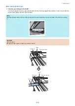
7. In the following service mode, execute either AB or Inch configuration tray width adjustment.
• To execute AB configuration adjustment
1. Highlight the service mode item.
• Service Mode > FEEDER > FUNCTION > TRY-A4
2. Align the Slide Guide with "A4/A3".
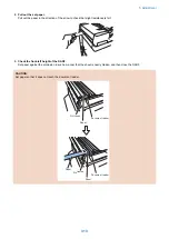
3. Highlight the service mode item.
• Service Mode > FEEDER > FUNCTION > TRY- A5R
4. Align the Slide Guide with "A5R".
5. Press the OK key and register the width of A5R.
• To execute Inch configuration adjustment
1. Highlight the service mode item.
• Service Mode > FEEDER > FUNCTION > TRY-LTR
2. Align the Slide Guide with "LTR/11x17".
3. Press the OK key and register the width of Letter.
4. Highlight the service mode item.
• Service Mode > FEEDER > FUNCTION > TRY- LTRR
5. Align the Slide Guide with "STMT/LTRR/LGL".
6. Press the OK key and register the width of LTRR.
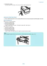
8. In the following service mode, output P-PRINT.
• Service Mode > COPIER > FUNCTION > MISC-P > P-PRINT
Keep the output P-PRINT in service book case.
5. Adjustment
299
Summary of Contents for imagerunner advance 4551i
Page 19: ...Product Overview 1 Product Lineup 7 Features 13 Specifications 16 Name of Parts 26 ...
Page 155: ...Periodical Service 3 Consumable Parts List 143 Cleaning Check Adjustment Locations 146 ...
Page 392: ...Error Jam Alarm 7 Overview 380 Error Code 383 Jam Code 509 Alarm Code 520 ...
Page 545: ...Service Mode 8 Overview 533 COPIER 549 FEEDER 845 SORTER 851 BOARD 871 ...
Page 892: ...Unpacking 1 2 1200 mm 840 mm 769 mm 1230 mm 2430 mm 3 9 Installation 879 ...
Page 895: ...3 4 NOTE Keep the removed screws for relocating the host machine 2x 5 6 7 9 Installation 882 ...
Page 896: ...8 9 10 1x Installing the Air Filter 1 9 Installation 883 ...
Page 897: ...2 3 Installing the Drum Unit 1 2 3 9 Installation 884 ...
Page 899: ...8 NOTE The screw removed at procedure 4 is used 1x 9 10 11 12 9 Installation 886 ...
Page 923: ...5 6 NOTE Use the screws and Rubber Caps removed in step 1 2x 7 2x 9 Installation 910 ...
Page 935: ...7 1x 8 9 6x 10 2x 9 Installation 922 ...
Page 936: ...11 Installing the NFC Kit 1 2 2x 3 TP M3x4 1x 9 Installation 923 ...
Page 938: ...4 5 1x 6 9 Installation 925 ...
Page 985: ...8 2x 2x TP M4x8 Black When installing the USB Keyboard 1 9 Installation 972 ...
Page 991: ...7 4x 8 1x 1x Lower Cover 9 1x 10 1x 1x 9 Installation 978 ...
Page 992: ...11 1x 1x 12 1x 13 TP M3x12 2x 14 4x TP M3x6 9 Installation 979 ...
Page 997: ...Installation Procedure 1 2 2x 3 2x 4 6x 5 4x 9 Installation 984 ...
Page 998: ...6 7 NOTE Do not close the Wire Saddle 1x 1x 8 9 9 Installation 985 ...
Page 1003: ...2 1x 1x 3 2x 2x 4 9 Installation 990 ...
Page 1012: ...2 1x 1x 3 2x 2x 4 9 Installation 999 ...
Page 1014: ...7 CAUTION The connector must be contacted TP㸹M3x6 3x 1x 8 4x 9 9 Installation 1001 ...
Page 1016: ...13 4x 14 15 Binding M4x16 Binding M3x16 2x M3x16 M4x16 16 Binding M4x6 1x 9 Installation 1003 ...
Page 1023: ...Installation Procedure Preparation 1 4x 2 1x 1x 3 2x 9 Installation 1010 ...
Page 1029: ...4 5 1x 1x 9 Installation 1016 ...
Page 1048: ...3 2x TP M3x8 Black 4 2x TP M3x6 5 9 Installation 1035 ...
Page 1053: ... Installing the Removable HDD Kit 1 2x 2x 2 3 1x 4 9 Installation 1040 ...
Page 1065: ...3 2x TP M3x8 Black 4 2x TP M3x6 5 9 Installation 1052 ...
Page 1071: ... Installing the Removable HDD Kit 1 2x 2x 2 3 1x 4 9 Installation 1058 ...


