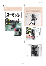

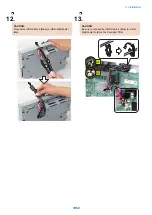


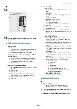


13.
14.
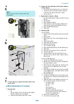
Connect the power plug of the host machine to the
power outlet.
■ HDD Initialization Procedure
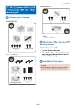
1. Requirements
1. PC
Service Support Tool in the version that supports
this host machine must be installed.
2. Cross Ethernet Cable (when SST is used)
2. Preparing for the Installation of the System Software
of Host machine
1. If both PC and the machine are on, turn them off.
2. Connect the PC and the host machine using an
Cross Ethernet cable. (when SST is used)
3. Turn on the PC.
3. Registering the system software
1. Insert the latest System Software into the PC using
the SST.
2. Start the SST.
3. Click 'Register Firmware'.
4. Select the drive where the system software has
been inserted, and click the [SEARCH] button.
5. Click the [REGISTER] button.
6. Click [OK].
4. Initializing HDD
<In case of SST>
1. Start the host machine with download mode in safe
mode.
2. Start the SST.
3. Select the model. Then, select [Single] and click
[Start].
4. Click [Format HDD].
5. Select [All], and click [Start].
6. Click [Execute Format].
7. The Format is executed.
8. Select [Shutdown/Restart], and click [Shutdown].
9. Click [OK]
10. The power of the host machine is turned OFF.
11. Terminate the SST.
12. Disconnect the Cross Ethernet Cable from the
machine, and connect the user's network cable to
the machine.
<In case of USB flash drive>
1. Connect the USB flash drive to the PC.
2. Start up SST, and click the USB icon displayed in
the target selection screen.
3. Select the drive, the model series, and the version
to be written to the USB flash drive, and click
[Confirm].
4. Click [Start], and after the version has been written
to the USB flash drive, click [OK] and then remove
the USB flash drive.
5. Terminate the SST.
6. Connect the USB flash drive to the host machine,
and start the host machine with download mode in
safe mode.
7. When the USB menu is displayed, press keys on
the Control Panel in the order shown below.
• [4]: Clear/Format
• [1]: Disk Format
• [0]: OK
• Press any keys.
• [C]: Return to menu
• [Reset] : Start shutdown sequence
• [0]: OK (The power of the host machine is
turned OFF automatically.)
8. Remove the USB flash drive.
9. Turn ON the main power switch.
■ Setting the Mirroring
1. Make a setting of mirroring.
• Specify "1" under "Service Mode (Level 1) >
COPIER > OPTION > FNC-SW > W/RAID".
2. Turn OFF/ON the main power of the host machine to
enable the setting value.
3. Make sure that the UI screen is activated correctly.
9. Installation
1067
Summary of Contents for imagerunner advance 4551i
Page 19: ...Product Overview 1 Product Lineup 7 Features 13 Specifications 16 Name of Parts 26 ...
Page 155: ...Periodical Service 3 Consumable Parts List 143 Cleaning Check Adjustment Locations 146 ...
Page 392: ...Error Jam Alarm 7 Overview 380 Error Code 383 Jam Code 509 Alarm Code 520 ...
Page 545: ...Service Mode 8 Overview 533 COPIER 549 FEEDER 845 SORTER 851 BOARD 871 ...
Page 892: ...Unpacking 1 2 1200 mm 840 mm 769 mm 1230 mm 2430 mm 3 9 Installation 879 ...
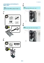
Page 895: ...3 4 NOTE Keep the removed screws for relocating the host machine 2x 5 6 7 9 Installation 882 ...
Page 896: ...8 9 10 1x Installing the Air Filter 1 9 Installation 883 ...
Page 897: ...2 3 Installing the Drum Unit 1 2 3 9 Installation 884 ...
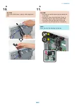
Page 899: ...8 NOTE The screw removed at procedure 4 is used 1x 9 10 11 12 9 Installation 886 ...
Page 923: ...5 6 NOTE Use the screws and Rubber Caps removed in step 1 2x 7 2x 9 Installation 910 ...
Page 935: ...7 1x 8 9 6x 10 2x 9 Installation 922 ...
Page 936: ...11 Installing the NFC Kit 1 2 2x 3 TP M3x4 1x 9 Installation 923 ...
Page 938: ...4 5 1x 6 9 Installation 925 ...
Page 985: ...8 2x 2x TP M4x8 Black When installing the USB Keyboard 1 9 Installation 972 ...
Page 991: ...7 4x 8 1x 1x Lower Cover 9 1x 10 1x 1x 9 Installation 978 ...
Page 992: ...11 1x 1x 12 1x 13 TP M3x12 2x 14 4x TP M3x6 9 Installation 979 ...
Page 997: ...Installation Procedure 1 2 2x 3 2x 4 6x 5 4x 9 Installation 984 ...
Page 998: ...6 7 NOTE Do not close the Wire Saddle 1x 1x 8 9 9 Installation 985 ...
Page 1003: ...2 1x 1x 3 2x 2x 4 9 Installation 990 ...
Page 1012: ...2 1x 1x 3 2x 2x 4 9 Installation 999 ...
Page 1014: ...7 CAUTION The connector must be contacted TP㸹M3x6 3x 1x 8 4x 9 9 Installation 1001 ...
Page 1016: ...13 4x 14 15 Binding M4x16 Binding M3x16 2x M3x16 M4x16 16 Binding M4x6 1x 9 Installation 1003 ...
Page 1023: ...Installation Procedure Preparation 1 4x 2 1x 1x 3 2x 9 Installation 1010 ...
Page 1029: ...4 5 1x 1x 9 Installation 1016 ...
Page 1048: ...3 2x TP M3x8 Black 4 2x TP M3x6 5 9 Installation 1035 ...
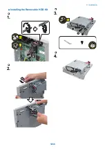
Page 1053: ... Installing the Removable HDD Kit 1 2x 2x 2 3 1x 4 9 Installation 1040 ...
Page 1065: ...3 2x TP M3x8 Black 4 2x TP M3x6 5 9 Installation 1052 ...
Page 1071: ... Installing the Removable HDD Kit 1 2x 2x 2 3 1x 4 9 Installation 1058 ...


