

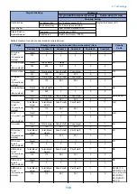
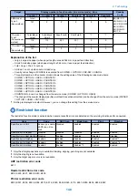


Target
Display number of each counter (in service mode) / item
Country
Code
Counter 1
Counter 2
Counter 3
Counter 4
Counter 5
Counter 6
AMS model
Type 2
(New method)
Total1
*1
*1
*1
*1
*1
ES/ SE/ PT/
NO/ DK/ FI/ PL/
HU/ CZ/ SI/ GR/
EE/ RU/ NL/
SK/ RO/ HR/
BG/ TR
101
0
0
0
0
0
ITA model
Type1
(Conventional
method)
Total(Black/
Large)
Total(Black/
Small)
Scan(Total1)
Print(Total1)
*1
*1
IT
112
113
501
301
0
0
ITA model Type
2
(New method)
Total1
*1
*1
*1
*1
*1
IT
101
0
0
0
0
0
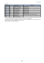
Explanation of the list
• Large: Large size paper (when paper length exceeds 364 mm in paper feed direction)
• Small: Small size paper (when paper length is 364 mm or less in paper feed direction)
• Total: Copy + Print; 1 count up
• 2-Sided: 1 count up when auto 2-sided copy
• Country code change of CONFIG is executed from COPIER > OPTION > FNC-SW > CONFIG.
• Three-digit number in the counter column shows the setting value of the following service mode items.
COPIER > OPTION > USER > COUNTER 1
COPIER > OPTION > USER > COUNTER 2
COPIER > OPTION > USER > COUNTER 3
COPIER > OPTION > USER > COUNTER 4
COPIER > OPTION > USER > COUNTER 5
COPIER > OPTION > USER > COUNTER 6
• COUNTER2 to 6 can be changed from the service mode (COPIER > OPTION > USER).
• The change of the counter display type (New method/Conventional method) can be changed from the service mode (COPIER
> OPTION > USER > CNT-SW).
*1: Nothing is displayed as default. However, you can change this setting from the service mode.
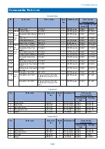
Restricted function
The restricted function mode is activated when several specific errors are detected so the surviving functions still can operate.
Item
Copy
ADF Scan
Book Scan
Finisher
Specific error in ADF
Book copy : enable-
dADF copy: disa-
bled
Disabled
Enabled
Enabled
Enabled
Specific error in Reader
Disabled
Disabled
Disabled
Enabled
Enabled
Specific error in Host machine Disabled
Enabled
Enabled
Disabled
Disabled
Specific error in Finisher
Enabled
Enabled
Enabled
Enabled
Enabled*1
Specific error in Finisher
Enabled
Enabled
Enabled
Enabled
Enabled *2
Specific error in pickup
Enabled
Enabled
Enabled *3
Enabled
Enabled
*1: Only the straight pass delivery is available. Stapling, aligning, punching are not available.
*2: Only the stapling is not available.
*3: Only the target paper source is not available.
ADF restriction error code
E413
Reader restriction error code
E202, E225, E227, E248, E280, E400
Printer restriction error code
E000, E001, E002, E003, E004, E010, E014, E020, E024, E025, E110, E261, E800, E805, E806, E840
2. Technology
140
Summary of Contents for imagerunner advance 4551i
Page 19: ...Product Overview 1 Product Lineup 7 Features 13 Specifications 16 Name of Parts 26 ...
Page 155: ...Periodical Service 3 Consumable Parts List 143 Cleaning Check Adjustment Locations 146 ...
Page 392: ...Error Jam Alarm 7 Overview 380 Error Code 383 Jam Code 509 Alarm Code 520 ...
Page 545: ...Service Mode 8 Overview 533 COPIER 549 FEEDER 845 SORTER 851 BOARD 871 ...
Page 892: ...Unpacking 1 2 1200 mm 840 mm 769 mm 1230 mm 2430 mm 3 9 Installation 879 ...
Page 895: ...3 4 NOTE Keep the removed screws for relocating the host machine 2x 5 6 7 9 Installation 882 ...
Page 896: ...8 9 10 1x Installing the Air Filter 1 9 Installation 883 ...
Page 897: ...2 3 Installing the Drum Unit 1 2 3 9 Installation 884 ...
Page 899: ...8 NOTE The screw removed at procedure 4 is used 1x 9 10 11 12 9 Installation 886 ...
Page 923: ...5 6 NOTE Use the screws and Rubber Caps removed in step 1 2x 7 2x 9 Installation 910 ...
Page 935: ...7 1x 8 9 6x 10 2x 9 Installation 922 ...
Page 936: ...11 Installing the NFC Kit 1 2 2x 3 TP M3x4 1x 9 Installation 923 ...
Page 938: ...4 5 1x 6 9 Installation 925 ...
Page 985: ...8 2x 2x TP M4x8 Black When installing the USB Keyboard 1 9 Installation 972 ...
Page 991: ...7 4x 8 1x 1x Lower Cover 9 1x 10 1x 1x 9 Installation 978 ...
Page 992: ...11 1x 1x 12 1x 13 TP M3x12 2x 14 4x TP M3x6 9 Installation 979 ...
Page 997: ...Installation Procedure 1 2 2x 3 2x 4 6x 5 4x 9 Installation 984 ...
Page 998: ...6 7 NOTE Do not close the Wire Saddle 1x 1x 8 9 9 Installation 985 ...
Page 1003: ...2 1x 1x 3 2x 2x 4 9 Installation 990 ...
Page 1012: ...2 1x 1x 3 2x 2x 4 9 Installation 999 ...
Page 1014: ...7 CAUTION The connector must be contacted TP㸹M3x6 3x 1x 8 4x 9 9 Installation 1001 ...
Page 1016: ...13 4x 14 15 Binding M4x16 Binding M3x16 2x M3x16 M4x16 16 Binding M4x6 1x 9 Installation 1003 ...
Page 1023: ...Installation Procedure Preparation 1 4x 2 1x 1x 3 2x 9 Installation 1010 ...
Page 1029: ...4 5 1x 1x 9 Installation 1016 ...
Page 1048: ...3 2x TP M3x8 Black 4 2x TP M3x6 5 9 Installation 1035 ...
Page 1053: ... Installing the Removable HDD Kit 1 2x 2x 2 3 1x 4 9 Installation 1040 ...
Page 1065: ...3 2x TP M3x8 Black 4 2x TP M3x6 5 9 Installation 1052 ...
Page 1071: ... Installing the Removable HDD Kit 1 2x 2x 2 3 1x 4 9 Installation 1058 ...


