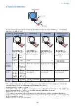


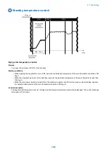
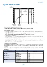


Fixing pressure roller cleaning sequence
Purpose
To prevent the dirt of the pressure roller causing the dirt of the paper back side.
Starting conditions
When the detected temperature of sub thermistor (front) or (rear) is higher 18 deg C or more than the one of the main thermistor.
Operation
After completion of the last rotation, the temperature control is executed so that the fixing heater turns on and the toner on the
pressure roller is melted to transfer it to the fixing film. After transferring the toner to the fixing film, the fixing motor is rotated
slightly to shift the nip area, so that re-transferring the toner to the pressure roller is prevented.
Completion conditions
This sequence is finished when either following condition is satisfied.
• After 5 seconds (maximum 10 sec) from shifting to the pressure roller cleaning sequence.
• When the next job is started during the pressure roller cleaning sequence.
Related Service Mode
• clean the fixing film
COPIER > FUNCTION > CLEANING > FIX-CLN
• Set fixing cln sequence execution temp
COPIER > OPTION > IMG-FIX > FIX-CLN
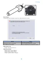
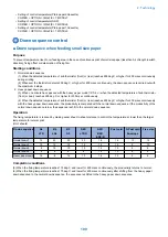
Fixing film edge cooling control
When making prints with the paper that the width is shorter than A4, to prevent temperature rise of non-feeding area, the fan
attached near the fixing assembly sends air and cools to the front and rear side of the fixing film.
For details of the fixing film edge cooling control,
“Fixing film edge cooling fan (rear)/(front) control” on page 137
Related Service Mode
• Setting for down sequence start temperature
COPIER > OPTION > IMG-FIX > EDG-WAIT
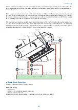
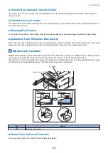
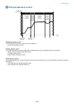
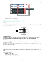
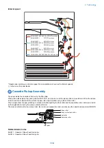
Paper loop amount control before fixing
Purpose
To get a proper image by avoiding a shock when the trailing edge of paper comes out of the registration roles, an appropriate
paper loop is formed between transfer roller and fixing roller.
Fixing film
Drum
Registration
roller
Pressure roller
Loop sensor(S6)
Transfer roller
Sensor: OFF
Sensor: ON
2. Technology
111
Summary of Contents for imagerunner advance 4551i
Page 19: ...Product Overview 1 Product Lineup 7 Features 13 Specifications 16 Name of Parts 26 ...
Page 155: ...Periodical Service 3 Consumable Parts List 143 Cleaning Check Adjustment Locations 146 ...
Page 392: ...Error Jam Alarm 7 Overview 380 Error Code 383 Jam Code 509 Alarm Code 520 ...
Page 545: ...Service Mode 8 Overview 533 COPIER 549 FEEDER 845 SORTER 851 BOARD 871 ...
Page 892: ...Unpacking 1 2 1200 mm 840 mm 769 mm 1230 mm 2430 mm 3 9 Installation 879 ...
Page 895: ...3 4 NOTE Keep the removed screws for relocating the host machine 2x 5 6 7 9 Installation 882 ...
Page 896: ...8 9 10 1x Installing the Air Filter 1 9 Installation 883 ...
Page 897: ...2 3 Installing the Drum Unit 1 2 3 9 Installation 884 ...
Page 899: ...8 NOTE The screw removed at procedure 4 is used 1x 9 10 11 12 9 Installation 886 ...
Page 923: ...5 6 NOTE Use the screws and Rubber Caps removed in step 1 2x 7 2x 9 Installation 910 ...
Page 935: ...7 1x 8 9 6x 10 2x 9 Installation 922 ...
Page 936: ...11 Installing the NFC Kit 1 2 2x 3 TP M3x4 1x 9 Installation 923 ...
Page 938: ...4 5 1x 6 9 Installation 925 ...
Page 985: ...8 2x 2x TP M4x8 Black When installing the USB Keyboard 1 9 Installation 972 ...
Page 991: ...7 4x 8 1x 1x Lower Cover 9 1x 10 1x 1x 9 Installation 978 ...
Page 992: ...11 1x 1x 12 1x 13 TP M3x12 2x 14 4x TP M3x6 9 Installation 979 ...
Page 997: ...Installation Procedure 1 2 2x 3 2x 4 6x 5 4x 9 Installation 984 ...
Page 998: ...6 7 NOTE Do not close the Wire Saddle 1x 1x 8 9 9 Installation 985 ...
Page 1003: ...2 1x 1x 3 2x 2x 4 9 Installation 990 ...
Page 1012: ...2 1x 1x 3 2x 2x 4 9 Installation 999 ...
Page 1014: ...7 CAUTION The connector must be contacted TP㸹M3x6 3x 1x 8 4x 9 9 Installation 1001 ...
Page 1016: ...13 4x 14 15 Binding M4x16 Binding M3x16 2x M3x16 M4x16 16 Binding M4x6 1x 9 Installation 1003 ...
Page 1023: ...Installation Procedure Preparation 1 4x 2 1x 1x 3 2x 9 Installation 1010 ...
Page 1029: ...4 5 1x 1x 9 Installation 1016 ...
Page 1048: ...3 2x TP M3x8 Black 4 2x TP M3x6 5 9 Installation 1035 ...
Page 1053: ... Installing the Removable HDD Kit 1 2x 2x 2 3 1x 4 9 Installation 1040 ...
Page 1065: ...3 2x TP M3x8 Black 4 2x TP M3x6 5 9 Installation 1052 ...
Page 1071: ... Installing the Removable HDD Kit 1 2x 2x 2 3 1x 4 9 Installation 1058 ...


