
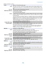

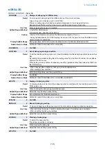
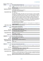


COPIER > OPTION > FNC-SW
CONFIG
1
Set country/area/lang/location/ppr size
Detail
To set the country/region, language, location, paper size configuration for multiple system software
in HDD.
Use Case
Upon user's request
Adj/Set/Operate Method
1) Select the setting item.
2) Switch with +/- key, and then press OK key.
3) Turn OFF/ON the main power switch.
Display/Adj/Set Range
XX YY.ZZ.AA
XX: Country/region
JP: Japan, US: United States, GB: England, FR: France, DE: Germany, IT: Italia, AU: Australia,
SG: Singapore, NL: Netherlands, KR: Korea, CN: China, TW: Taiwan, ES: Spain, SE: Sweden,
PT: Portugal, NO: Norway, DK: Denmark, FI: Finland, PL: Poland, HU: Hungary, CZ: Czech, SI:
Slovenia, GR: Greek, EE: Estonia, RU: Russia, AD: Andorra, AL: Albania, AM: Armenia, AR:
Argentine, AT: Austria, BA: Bosnia Herzegovina, BE: Belgium, BG: Bulgaria, BO: Bolivia, BR:
Brazil, CA: Canada, CH: Switzerland, CL: Chile, CY: Cyprus, HR: Croatia, ID: Indonesia, IE:
Ireland, IL: Israel, IN: India, IS: Iseland, LU: Luxembourg, LV: Latvia, MX: Mexico, MY: Malaysia,
NZ: New Zealand, PE: Peru, PH: Philippine, PY: Paraguay, RO: Romania, SK: Slovakia, TH:
Thailand, TR: Turkey, UA: Ukraine, UY: Uruguay, VE: Venezuela, VN: Vietnam
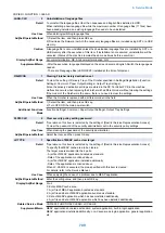
YY: Language (Fixed; e.g. ja: Japanese)
ZZ: Location (Fixed; e.g. 00: CANON)
AA: Paper size configuration (00: AB configuration, 01: Inch configuration, 02: A configuration, 03:
Inch/AB configuration)
Related Service Mode
COPIER> OPTION> FNC-SW> MODEL-SZ
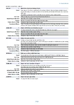
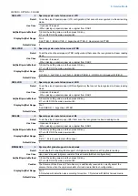
W/SCNR
1
Setting of Reader Unit installation
Detail
To set installation of the Reader Unit.
1 (Installed) is automatically selected once the Reader Unit is detected at the start of the machine.
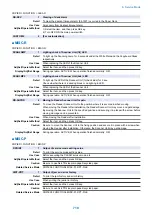
Use Case
When installing/removing the Reader Unit
Adj/Set/Operate Method
1) Enter the setting value, and then press OK key.
2) Turn OFF/ON the main power switch.
Display/Adj/Set Range
0 to 1
0: Not installed, 1: Installed
Default Value
0 (Printer model)/1 (Copier model)
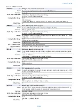
FAN-EXTN
2
Fan drive extension mode after job
Detail
Fan drive extension time mode after job.
Use Case
Upon user's request
Adj/Set/Operate Method
Enter the setting value, and then press OK key.
Display/Adj/Set Range
0 to 1
0: OFF, 1: ON
Default Value
1
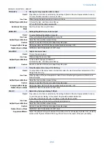
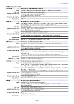
ORG-LGL
2
Special ppr size set at stream read: LGL
Detail
To set the size of special paper (LGL configuration) that cannot be recognized in stream reading
mode.
Use Case
- Upon user's request
- When picking up special paper size original from DADF
Adj/Set/Operate Method
1) Enter the setting value, and then press OK key.
2) Turn OFF/ON the main power switch.
Display/Adj/Set Range
0 to 12
0: LEGAL-R, 1: FOOLSCAP-R/FOLIO-R, 2: OFICIO-R, 3: Not used, 4: Australian FOOLSCAP-R,
5: Ecuador OFICIO-R, 6: Bolivia OFICIO-R, 7: Argentine OFICIO-R, 8: Not used, 9: Government
LEGAL-R, 10: Mexico OFICIO-R, 11: F4A, 12: India LEGAL-R
Default Value
0
8. Service Mode
717
Summary of Contents for imagerunner advance 4551i
Page 19: ...Product Overview 1 Product Lineup 7 Features 13 Specifications 16 Name of Parts 26 ...
Page 155: ...Periodical Service 3 Consumable Parts List 143 Cleaning Check Adjustment Locations 146 ...
Page 392: ...Error Jam Alarm 7 Overview 380 Error Code 383 Jam Code 509 Alarm Code 520 ...
Page 545: ...Service Mode 8 Overview 533 COPIER 549 FEEDER 845 SORTER 851 BOARD 871 ...
Page 892: ...Unpacking 1 2 1200 mm 840 mm 769 mm 1230 mm 2430 mm 3 9 Installation 879 ...
Page 895: ...3 4 NOTE Keep the removed screws for relocating the host machine 2x 5 6 7 9 Installation 882 ...
Page 896: ...8 9 10 1x Installing the Air Filter 1 9 Installation 883 ...
Page 897: ...2 3 Installing the Drum Unit 1 2 3 9 Installation 884 ...
Page 899: ...8 NOTE The screw removed at procedure 4 is used 1x 9 10 11 12 9 Installation 886 ...
Page 923: ...5 6 NOTE Use the screws and Rubber Caps removed in step 1 2x 7 2x 9 Installation 910 ...
Page 935: ...7 1x 8 9 6x 10 2x 9 Installation 922 ...
Page 936: ...11 Installing the NFC Kit 1 2 2x 3 TP M3x4 1x 9 Installation 923 ...
Page 938: ...4 5 1x 6 9 Installation 925 ...
Page 985: ...8 2x 2x TP M4x8 Black When installing the USB Keyboard 1 9 Installation 972 ...
Page 991: ...7 4x 8 1x 1x Lower Cover 9 1x 10 1x 1x 9 Installation 978 ...
Page 992: ...11 1x 1x 12 1x 13 TP M3x12 2x 14 4x TP M3x6 9 Installation 979 ...
Page 997: ...Installation Procedure 1 2 2x 3 2x 4 6x 5 4x 9 Installation 984 ...
Page 998: ...6 7 NOTE Do not close the Wire Saddle 1x 1x 8 9 9 Installation 985 ...
Page 1003: ...2 1x 1x 3 2x 2x 4 9 Installation 990 ...
Page 1012: ...2 1x 1x 3 2x 2x 4 9 Installation 999 ...
Page 1014: ...7 CAUTION The connector must be contacted TP㸹M3x6 3x 1x 8 4x 9 9 Installation 1001 ...
Page 1016: ...13 4x 14 15 Binding M4x16 Binding M3x16 2x M3x16 M4x16 16 Binding M4x6 1x 9 Installation 1003 ...
Page 1023: ...Installation Procedure Preparation 1 4x 2 1x 1x 3 2x 9 Installation 1010 ...
Page 1029: ...4 5 1x 1x 9 Installation 1016 ...
Page 1048: ...3 2x TP M3x8 Black 4 2x TP M3x6 5 9 Installation 1035 ...
Page 1053: ... Installing the Removable HDD Kit 1 2x 2x 2 3 1x 4 9 Installation 1040 ...
Page 1065: ...3 2x TP M3x8 Black 4 2x TP M3x6 5 9 Installation 1052 ...
Page 1071: ... Installing the Removable HDD Kit 1 2x 2x 2 3 1x 4 9 Installation 1058 ...


