


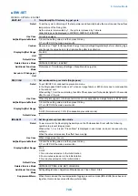


■ ENV-SET
COPIER > OPTION > ENV-SET
ENVP-INT
1
Temp&hmdy/Fix Film temp log get cycle
Detail
To set the cycle to obtain log of the temperature and humidity inside the machine and the surface
temperature of the Fixing Film.
As the value is incremented by 1, the cycle is increased by 1 minute.
Collected log can be displayed in COPIER> DISPLAY> ENVRNT.
Use Case
At trouble analysis
Adj/Set/Operate Method
1) Enter the setting value, and then press OK key.
2) Turn OFF/ON the main power switch.
Caution
Be sure to set "High" for [Sleep Mode Energy Use] in [Settings/Registration] before collecting logs,
and change the value back to its original setting after log collection.
Display/Adj/Set Range
0 to 480
Unit
min
Default Value
60
Related Service Mode
COPIER> DISPLAY> ENVRNT
Additional Functions
Mode
Preferences> Timer/Energy Settings> Sleep Mode Energy Use
Amount of Change per
Unit
1
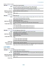
DRY-CISU
1
Set condensation prev mode (Single pass)
Detail
To set ON/OFF of condensation prevention mode.
In the Single pass DADF model, set 1 when an image failure or E302 occurs due to condensation
in the scanner unit.
When setting 1, from the next startup, the LED of the scanner unit for back side lights for 30 seconds
after the end of the job.
Use Case
When droplets appear on the Scanner Unit due to condensation and image failure or E302 occurs
Adj/Set/Operate Method
1) Enter the setting value, and then press OK key.
2) Turn OFF/ON the main power switch.
Display/Adj/Set Range
0 to 1
0: OFF (Normal mode), 1: ON (Condensation prevention mode)
Default Value
0
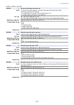
IMG-BLD1
2
Set image smear prevention mode
Detail
To warm around the Developing Assembly and the Photosensitive Drum with the following
operation to prevent image smear.
When either 1, 2 or 3 is set, "Clean Drum" is displayed in user mode, and user can execute only
setting 2.
When the value is increased, the effect becomes big.
Use Case
When image smear occurs
Adj/Set/Operate Method
1) Enter the setting value, and then press OK key.
2) Turn OFF/ON the main power switch.
Display/Adj/Set Range
0 to 3
0: OFF
1: Two minutes extension in the initial rotation
2: Four minutes extension in the initial rotation
3: Six minutes extension in the initial rotation
Default Value
0
Related Service Mode
COPIER> OPTION> ENV-SET> IMG-BLD4
Additional Functions
Mode
Settings/Registration> Adjustment/Maintenance> Clean Drum> Start
Supplement/Memo
When this mode and the low temperature fogging prevention mode (IMG-BLD4) have been set
together, this mode becomes effective preferentially.
8. Service Mode
748
Summary of Contents for imagerunner advance 4551i
Page 19: ...Product Overview 1 Product Lineup 7 Features 13 Specifications 16 Name of Parts 26 ...
Page 155: ...Periodical Service 3 Consumable Parts List 143 Cleaning Check Adjustment Locations 146 ...
Page 392: ...Error Jam Alarm 7 Overview 380 Error Code 383 Jam Code 509 Alarm Code 520 ...
Page 545: ...Service Mode 8 Overview 533 COPIER 549 FEEDER 845 SORTER 851 BOARD 871 ...
Page 892: ...Unpacking 1 2 1200 mm 840 mm 769 mm 1230 mm 2430 mm 3 9 Installation 879 ...
Page 895: ...3 4 NOTE Keep the removed screws for relocating the host machine 2x 5 6 7 9 Installation 882 ...
Page 896: ...8 9 10 1x Installing the Air Filter 1 9 Installation 883 ...
Page 897: ...2 3 Installing the Drum Unit 1 2 3 9 Installation 884 ...
Page 899: ...8 NOTE The screw removed at procedure 4 is used 1x 9 10 11 12 9 Installation 886 ...
Page 923: ...5 6 NOTE Use the screws and Rubber Caps removed in step 1 2x 7 2x 9 Installation 910 ...
Page 935: ...7 1x 8 9 6x 10 2x 9 Installation 922 ...
Page 936: ...11 Installing the NFC Kit 1 2 2x 3 TP M3x4 1x 9 Installation 923 ...
Page 938: ...4 5 1x 6 9 Installation 925 ...
Page 985: ...8 2x 2x TP M4x8 Black When installing the USB Keyboard 1 9 Installation 972 ...
Page 991: ...7 4x 8 1x 1x Lower Cover 9 1x 10 1x 1x 9 Installation 978 ...
Page 992: ...11 1x 1x 12 1x 13 TP M3x12 2x 14 4x TP M3x6 9 Installation 979 ...
Page 997: ...Installation Procedure 1 2 2x 3 2x 4 6x 5 4x 9 Installation 984 ...
Page 998: ...6 7 NOTE Do not close the Wire Saddle 1x 1x 8 9 9 Installation 985 ...
Page 1003: ...2 1x 1x 3 2x 2x 4 9 Installation 990 ...
Page 1012: ...2 1x 1x 3 2x 2x 4 9 Installation 999 ...
Page 1014: ...7 CAUTION The connector must be contacted TP㸹M3x6 3x 1x 8 4x 9 9 Installation 1001 ...
Page 1016: ...13 4x 14 15 Binding M4x16 Binding M3x16 2x M3x16 M4x16 16 Binding M4x6 1x 9 Installation 1003 ...
Page 1023: ...Installation Procedure Preparation 1 4x 2 1x 1x 3 2x 9 Installation 1010 ...
Page 1029: ...4 5 1x 1x 9 Installation 1016 ...
Page 1048: ...3 2x TP M3x8 Black 4 2x TP M3x6 5 9 Installation 1035 ...
Page 1053: ... Installing the Removable HDD Kit 1 2x 2x 2 3 1x 4 9 Installation 1040 ...
Page 1065: ...3 2x TP M3x8 Black 4 2x TP M3x6 5 9 Installation 1052 ...
Page 1071: ... Installing the Removable HDD Kit 1 2x 2x 2 3 1x 4 9 Installation 1058 ...


