Asterion DC Multioutput ASA Series Operational Manual
M330516-01
2-29
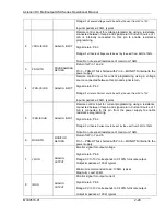
Pin #
Ethernet Signal
EIA/TIA 568A
EIA/TIA 568B
Crossover
8
Transmit/Receive Data 3 -
Brown with white stripe or
solid brown
Brown with white stripe or
solid brown
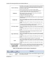
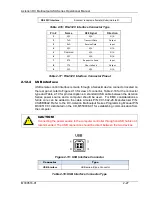
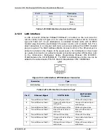
Table 2-21: LAN Interface 8P8C Modular Connector Pinout
2.12.6
GPIB interface
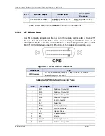
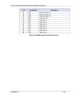
A GPIB connector is located on the rear panel for remote control; refer to Figure 2-15
for rear view of connector, Table 2-22 for connector type and Table 2-23 for pin
descriptions. Refer to the DC-Asterion Multioutput Series Programming Manual P/N
M330517-01 distributed on the CD, M550008-01 for establishing communication.
Figure 2-15: GPIB interface Connector
Connector
Type
GPIB Interface
PCB D-Sub Connectors, Receptacle, Cable-to-Board, 24 Position
TE Connectivity P/N: 5554923-1
Table 2-22: GPIB Interface Connector Type
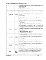
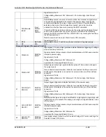
Pin #
GPIB Signal
Description
1
DIO1
Data Input/ Output bit
2
DIO2
Data Input/ Output bit
3
DIO3
Data Input/ Output bit
4
DIO4
Data Input/ Output bit
5
EOI
End- Or- Identity
6
DAV
Data Valid
7
NRFD
Not Ready for Data
8
NDAC
Not Data Accepted
9
IFC
Interface Clear
10
SRQ
Service Request
11
ATN
Attention
12
SHIELD
Tied to Digital Ground
13
DIO5
Data Input/ Output bit


