Asterion DC Multioutput ASA Series Operational Manual
M330516-01
2-13
CAUTION!
Input AC voltage type “E”: Do not connect an AC voltage that is greater than 528
VAC, line-to-line for 3-Phase input. Exceeding the maximum AC input voltage could
result in damage to the unit. Single phase input is not supported with voltage type
“E”
CAUTION!
A ground wire must be connected from the rear panel safety-ground terminal or the
rear panel safety ground stud to the utility power distribution earth protection-
ground.
2.9
DC Output and Remote Sense power
connections
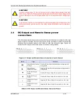
The DC output and remote sense connector for each channel is located on the rear
panel. Figure 2-7 shows the rear panel view of the connector. Table 2-6 shows the
functions and connector pinout, and Table 2-7 lists the connector type. Figure 2-8
shows the DC output and remote sense connection wiring details.
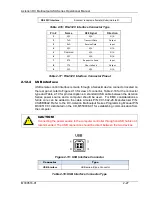
Figure 2-7: Output and Remote Sense Connector of each channel
Name
Type
Function
S+
Remote Sense Positive
DC Input
Positive DC input from the point where voltage needs to
be regulated
S-
Remote Sense
Negative DC Input
Negative DC input from the point where voltage needs to
be regulated
+
Positive DC Power
Output
Positive DC Power Output for connection to the Load
+
Positive DC Power
Output
Positive DC Power Output for connection to the Load
-
Negative DC Power
Output
Negative DC Power Output for connection to the Load
-
Negative DC Power
Output
Negative DC Power Output for connection to the Load
Table 2-6: DC Output and Remote Sense Connector Pinout

