Asterion DC Multioutput ASA Series Operational Manual
M330516-01
3-41
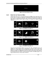
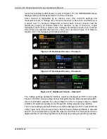
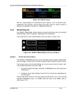
menu that is displayed after power-on, refer to Figure 3-16. The DASHBOARD screen
displays settings and measurement for all three channels.
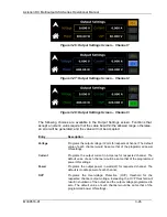
Active channel is highlighted by its channel color. First channel’s settings and
measurements are in Orange color. Second channel is in Blue color and third one is
in Green color. To program Voltage and current of each channel, channel must be
selected by tapping on channel button. For example, on tap of channel 3, it gets
highlighted, and it turns to Green color. Voltage and settings box also turn to Green
color. Other non-selected channels are in Grey color as shown Figure 3-18. Refer to
Section 3.4.2.1 for navigating to Dashboard Screen.
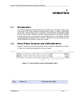
Figure 3-16: Dashboard Screen
– Channel 1
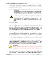
Figure 3-17: Dashboard Screen
– Channel 2
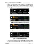
Figure 3-18: Dashboard Screen
– Channel 3
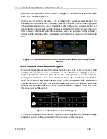
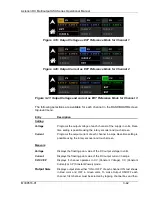
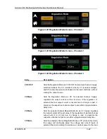
The Voltage settings parameter field box would be displayed as EXT in text (refer
Figure 3-19) if the corresponding channel Voltage Reference Mode is selected as EXT.
User is restricted to program the output voltage from the front panel screen or digital
interface. It could be programed only through the analog programming interface.
The Current settings parameter field box would be displayed as EXT in text (External)
(refer Figure 3-20) if the corresponding channel Current Reference Mode is selected
as EXT. User is restricted to program the output current from the front panel screen or
digital interface. It could be programed only through the analog programming interface.

