Asterion DC Multioutput ASA Series Operational Manual
M330516-01
3-40
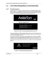
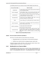
The following top-level menu choices can be accessed through the touchscreen:
Top-Level Screen Menu
Menu Description
DASHBOARD
Provides setting and measurement of output parameters: voltage and
current for individual channels.
OUTPUT PROGRAM
Provides setting of voltage, current, power, Regulation Mode, Output
state, and OVP (Over Voltage Protection) for individual channels.
MEASUREMENT
Provides Measurements of Output Voltage and Current, Output State
and Regulation Mode for individual channels.
CONFIGURATION
Provides setup of
P
ower
ON S
tates (PONS), User V/I limit and
Measurement Settings for individual channels.
RAMP
Provides Voltage and Current Ramp functions for individual channels.
OUTPUT ON DELAY
Provides setup to Turn ON all three channels Output individually in a
sequence with specified time delay.
CONTROL INTERFACE
Provides setup of remote digital interfaces:
RS232, GPIB, LAN, Analog, and USB.
SYSTEM SETTINGS
Provides display of firmware versions, hardware parameter limits,
brightness of the display, Factory Default settings, Last calibrated
Date, System status for individual channels and default screen
timeout.
Table 3-2: Home Screen Menu Content
3.4.2.1
N
AVIGATING BETWEEN
H
OME
S
CREEN
M
ENUS
Each menu in the Home Screen can be reached in one of two ways:
•
Tapping selected menu on Home Screen of the front panel touchscreen.
•
Scrolling to menu with the encoder and depressing the encoder switch.
Tapping the Up-arrow button will return to the previously selected screen menu.
Tapping the HOME button will return to the Home Screen.
3.4.3
Dashboard Screen Top-Level Menu
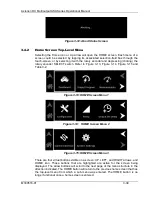
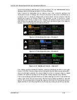
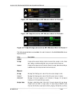
The DASHBOARD screen top-level menu is used to change output parameters and
simultaneously view output measurements. The most used output parameters are
shown in the DASHBOARD screen menu. The DASHBOARD screen is the default


